3-10 PULL OUT EXTENSIONS
DANGER
DO NOT OPERATE IF ANY EXTENSION
IS NOT LOCKED IN PLACE BY SPRING
LOADED LOCKING PIN. INSPECT ALL
EXTENSIONS TO INSURE EACH IS
LOCKED SECURELY IN POSITION BY
THE SPRING LOADED LOCKING PIN.
CAUTION
DO NOT PULL EXTENSIONS OUT OF
TRAILER FRAME WITHOUT ADE-
QUATE SUPPORT. FAILURE DO SO
MAY CAUSE INJURY.
3-10.1
Pull out extensions are adjustable in six
inch increments. Extension lock pin can be
held in released position when pulled back
and rotated one quarter turn into catch.
3-10.2
Adjust pull out to desired extended po-
sition and trip lock pin to secure.
WARNING
1. DO NOT OVERLOAD EXTENSIONS.
OVERWIDTH RATINGS ARE GIVEN IN
STANDARD SPECIFICATIONS.
2. DO NOT SECURE LOAD TO OVER-
WIDTHS OR UNDERCARRIAGE. SE-
CURE LOAD FRAME TO MOUNTED D-
RINGS OR GOTCHAS LOCATED IN
THE APPROACH PLATE AND FRAME
BEAM FLANGES.
3-10.3
Additional blocking or planking may be
used to support load wheels/tracks.
(See
Figure 3-4)
3-10.4
Install the flag holders in the second
hole of the front, center, and rear overwidth
tubes and secure with lock washer and wing
nut so the flag mounting tube is pointing up-
ward. Secure approved flags in the mounting
tube with the spring loaded retaining pin.
Reference FMCSR Part 393.87 and applica-
ble state and local regulations concerning
flags on projecting loads.
3-10.5
If required, display oversize load signs.
3-9
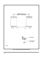
Figure 3-4 Pull Out Extensions
Содержание 825A
Страница 3: ...MODEL 825A 835 DETACHABLE TRAILER OPERATOR S MANUAL PURCHASED FROM DATE ADDRESS PHONE NO SERIAL NO i...
Страница 8: ......
Страница 12: ......
Страница 14: ...3 2 Figure 3 1 Model 825 Trailer Terminology Figure 3 2 Service Hookups...
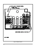
Страница 18: ...3 6 Figure 3 3 Hydraulic Controls...
Страница 22: ...3 10 Figure 3 5 Swingout Outrigger Platform Extension...
Страница 24: ...3 12 Figure 3 6 Gooseneck Attachment to Frame...
Страница 34: ......
Страница 36: ...4 2 Figure 4 1 Lubrication Points...
Страница 40: ...4 6 Figure 4 2 Model 825A Wiring Diagram...
Страница 43: ...4 9 Figure 4 4 Tandem Axle Air Ride Suspension System...
Страница 44: ...4 10 Figure 4 5 Tandem Axle W Flip Air Ride Suspension System...
Страница 47: ...4 13 Figure 4 8 Checking Axle Alignment Figure 4 9 Examples of Camber...
Страница 52: ...4 18 Figure 4 12 Axle and Brake Assembly...
Страница 59: ...4 25 Figure 4 18 Mounting Tires and Wheels Figure 4 19 Stud Tightening Sequence...
Страница 69: ...NOTES 5 9...
Страница 70: ......


