


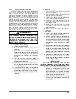


4-11.3
Mounting Tire and Wheel
a.
Make sure that all mounting surfaces are
clean and free of rust, dirt or paint. A wire
brush may be used to clean these surfaces
(See Figure 4-19)
.
b.
Position the inner disc wheel over the studs,
being careful not to damage the stud threads.
Make sure that the disc wheel is flat against
the mounting surface and that there is clear-
ance between the disc wheel taper and brake
drum.
c.
Position the outer disc wheel being careful
not to damage the threads. Be sure the valve
stems for both the inner and outer tire are ac-
cessible.
d.
Install
the
flange
nut
and
tighten
to
50
foot-
pounds
using
the
sequence
in
Figure
Then
tighten
to
full
torque
of
450
to
5
0
0
foot-
pounds.
e.
Torque
will
drop
after
the
first
50
to
100
miles
of
operation.
Check
the
nuts
for
proper
torque
after
this
interval
and
retighten
them.
WARNING
USE A TORQUE WRENCH TO ASSURE
PROPER TORQUE. INSUFFICIENT
TORQUE CAN CAUSE STUD BREAK-
AGE AND DAMAGE WHEEL PILOTS.
OVERTORQUE CAN OVERSTRESS
THE STUDS AND STRIP THE
THREADS.
4-29
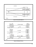
Figure 4-19 Mounting Tires and Wheels
Figure 4-20 Stud Tightening Sequence
Содержание 600B Series
Страница 3: ...MODEL 600B SERIES SEMITRAILER OPERATOR S MANUAL PURCHASED FROM DATE ADDRESS PHONE NO SERIAL NO i...
Страница 8: ......
Страница 12: ......
Страница 14: ...3 2 Figure 3 1 Front Trailer Terminology Figure 3 2 Rear Trailer Terminology...
Страница 18: ...3 6 Figure 3 4 Hydraulic Controls...
Страница 26: ...3 14 Figure 3 7 Steps for Loading and Unloading...
Страница 32: ...3 20 Figure 3 10 Dock Leveler Operation...
Страница 38: ...3 26 Figure 3 14 Rear Impact Guard and Antilock Brake System...
Страница 42: ...4 2 Figure 4 1 Lubrication Points...
Страница 48: ...4 8 Figure 4 3 600B Wiring Diagram...
Страница 49: ...4 9 Figure 4 4 Remote Wiring Diagram...
Страница 52: ...4 12 Figure 4 5 Tandem Axle Air Ride Suspension System Figure 4 6 Air Ride Height Adjustment...
Страница 54: ...4 14 Figure 4 7 Triple Axle Air Ride Suspension System...
Страница 57: ...4 17 Figure 4 9 Checking Axle Alignment Figure 4 10 Examples of Camber...
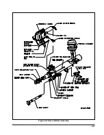
Страница 61: ...4 21 Figure 4 13 Axle and Brake Assembly...
Страница 71: ...4 31 Figure 4 21 Dock Leveler Leg Assembly...
Страница 73: ...4 33 Figure 4 22 Crank Landing Gear Assembly...
Страница 84: ...NOTES 5 10...


