


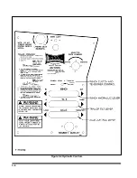


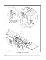


3-10 AXLE CONTROL LEVER
The
AXLE CONTROL
lever
(See Figure 3-4)
is located on the control panel. It is the top lever
with three positions:
LOAD
In this position, the undercarriage
slides forward for loading.
CENTER
This is the neutral position.
TRANSPORT
In this position, the undercarriage
slides to the rear. The undercarriage
must be in the rear-most position for
transport.
3-11 SWINGOUT OUTRIGGER PLATFORM EXTENSION SET-UP
(OPTION)(See Figure 3-5)
3-11.1
Unlatch and fold out swing-out outrig-
gers.
3-11.2
Unlatch pull-out extension by pulling
spring loaded latch pin. Slide extension out
until it latches again.
3-11.3
Place planks on outriggers and assem-
ble end to end using braces, 3/8"-16 x 2-1/4"
bolts, washers, and nuts.
3-11.4
Plank joints must be centered on outrig-
gers.
3-11.5
To remove pull-out extension, reverse
3-11.6
Remove only two bolts for each joint as
shown in
Figure 3-5.
Leave braces attached
to boards for storage.
3-10
Figure 3-5 Outrigger Platform Extension
Содержание 600B Series
Страница 3: ...MODEL 600B SERIES SEMITRAILER OPERATOR S MANUAL PURCHASED FROM DATE ADDRESS PHONE NO SERIAL NO i...
Страница 8: ......
Страница 12: ......
Страница 14: ...3 2 Figure 3 1 Front Trailer Terminology Figure 3 2 Rear Trailer Terminology...
Страница 18: ...3 6 Figure 3 4 Hydraulic Controls...
Страница 26: ...3 14 Figure 3 7 Steps for Loading and Unloading...
Страница 32: ...3 20 Figure 3 10 Dock Leveler Operation...
Страница 38: ...3 26 Figure 3 14 Rear Impact Guard and Antilock Brake System...
Страница 42: ...4 2 Figure 4 1 Lubrication Points...
Страница 48: ...4 8 Figure 4 3 600B Wiring Diagram...
Страница 49: ...4 9 Figure 4 4 Remote Wiring Diagram...
Страница 52: ...4 12 Figure 4 5 Tandem Axle Air Ride Suspension System Figure 4 6 Air Ride Height Adjustment...
Страница 54: ...4 14 Figure 4 7 Triple Axle Air Ride Suspension System...
Страница 57: ...4 17 Figure 4 9 Checking Axle Alignment Figure 4 10 Examples of Camber...
Страница 61: ...4 21 Figure 4 13 Axle and Brake Assembly...
Страница 71: ...4 31 Figure 4 21 Dock Leveler Leg Assembly...
Страница 73: ...4 33 Figure 4 22 Crank Landing Gear Assembly...
Страница 84: ...NOTES 5 10...


