


3-21 REMOTE CONTROL (OPTION)
3-21.1
The wired remote control plugs into an
electrical receptacle usually located on the
hydraulic control panel. Optional receptacle
locations are on the rear street side or both
rear street and rear curb sides. The wired re-
mote is available as a single, dual, or triple
function.
3-21.2
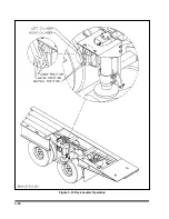
A wireless radio remote control is also
available in triple function
(See Figure 3-13).
3-21.3
The single function wired remote oper-
ates like the
WINCH HYDRAULIC LEVER
(See Section 3-16.1).
3-21.4
The dual function wired remote oper-
ates the winch in/out and either the tilt, axle,
or winch tension: or the tilt and axle.
a.
The selector switch at the top of the remote
box selects the function to be operated
(WINCH HYDRAULIC, TRAILER TILT, AXLE
CONTROL, OR WINCH TENSIONER)
.
b.
The two buttons will function like the control
levers for the
WINCH HYDRAULIC (See Sec-
tion 3-16.1), TRAILER TILT (See Section
3-9), AXLE CONTROL (See Section 3-10),
or
WINCH TENSIONER (See Section
3-21.5
The triple function wired remote oper-
ates the winch in/out, tilt, and either the axle
or winch tension.
a.
There are three switches which function like
the control levers for the
WINCH HYDRAU-
LIC (See Section 3-16.1), TRAILER TILT
(See Section 3-9), AXLE CONTROL (See
Section 3-10),
or
WINCH TENSIONER (See
Section 3-16.2).
3-21.6
The wireless radio remote has six mo-
mentary push button switches that operate
the functions as labeled on the hand held re-
mote.
IMPORTANT
ON WINCHES WITH THE AIR TENSION OPTION,
THE WINCH TENSION IS ENGAGED AUTO-
MATICALLY WHEN THE SWITCH IS TURNED
TO WINCH IN/OUT. THE WINCH TENSION
SWITCH ON EITHER THE REMOTE OR THE
CONTROL PANEL MUST BE USED TO DISEN-
GAGE THE WINCH.
3-25
Figure 3-13 Examples of Remote Control Options
Содержание 600B Series
Страница 3: ...MODEL 600B SERIES SEMITRAILER OPERATOR S MANUAL PURCHASED FROM DATE ADDRESS PHONE NO SERIAL NO i...
Страница 8: ......
Страница 12: ......
Страница 14: ...3 2 Figure 3 1 Front Trailer Terminology Figure 3 2 Rear Trailer Terminology...
Страница 18: ...3 6 Figure 3 4 Hydraulic Controls...
Страница 26: ...3 14 Figure 3 7 Steps for Loading and Unloading...
Страница 32: ...3 20 Figure 3 10 Dock Leveler Operation...
Страница 38: ...3 26 Figure 3 14 Rear Impact Guard and Antilock Brake System...
Страница 42: ...4 2 Figure 4 1 Lubrication Points...
Страница 48: ...4 8 Figure 4 3 600B Wiring Diagram...
Страница 49: ...4 9 Figure 4 4 Remote Wiring Diagram...
Страница 52: ...4 12 Figure 4 5 Tandem Axle Air Ride Suspension System Figure 4 6 Air Ride Height Adjustment...
Страница 54: ...4 14 Figure 4 7 Triple Axle Air Ride Suspension System...
Страница 57: ...4 17 Figure 4 9 Checking Axle Alignment Figure 4 10 Examples of Camber...
Страница 61: ...4 21 Figure 4 13 Axle and Brake Assembly...
Страница 71: ...4 31 Figure 4 21 Dock Leveler Leg Assembly...
Страница 73: ...4 33 Figure 4 22 Crank Landing Gear Assembly...
Страница 84: ...NOTES 5 10...


