


WARNING
THE INSTALLATION GUIDE MUST BE
USED WHEN INSTALLING OR REIN-
STALLING AUTOMATIC SLACK AD-
JUSTER. FAILURE TO DO SO MAY RE-
SULT IN IMPROPERLY ADJUSTED
BRAKES WHICH MAY CAUSE BRAKE
DAMAGE OR LEAD TO BRAKE FAIL-
URE.
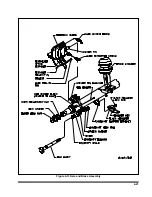
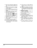
a. Operational Check (See Figure 4-14)
1.
Block wheels to prevent vehicle from
rolling.
2.
Check that the push rod is fully retracted,
apply air to release spring brake.
3.
Turn adjustment hex counterclockwise to
create an excessive clearance condition.
(A ratcheting sound will occur.)
4.
Make a full service brake application. On
release, allow sufficient time for brake to
fully retract. During the brake release,
observe rotation of the adjustment hex
(attach a wrench on the hex to make this
movement easier to see). This rotation
indicates that an excessive clearance
condition has been determined by the slack
adjuster, and it is making an adjustment to
compensate. On each subsequent brake
release the amount of adjustment and push
rod travel will be reduced until the desired
clearance is achieved
5.
The push rod stroke should be 1 1/2" to 2"
with an 100 to 105 PSI service brake
application.
6.
Measure the movement of the push rod
from the completely released position to
the applied position by marking the push
rod where it exits the air chamber before
and after application.
7.
If the brakes have been running tight, the
control arm location should be checked.
WARNING
IF THE ADJUSTER APPEARS NOT TO
BE OPERATING, CHECK THE OTHER
BRAKE COMPONENTS FOR PROPER
FUNCTION AND ELIMINATE ANY BIND-
ING. RECHECK THE AUTOMATIC
SLACK ADJUSTER. IF THE ADJUSTER
IS NOT FUNCTIONING, THE UNIT
MUST BE REPLACED BECAUSE FAIL-
URE OF PROPER ADJUSTMENT
FUNCTION WILL RESULT IN LOSS OF
BRAKES.
b. Replacing Slack Adjuster (See Figure
1.
Chock wheels to prevent vehicle from
rolling. Release spring and service brake.
Air chamber push rod must be
fully
released.
2.
To maintain a fully released parking brake,
a minimum of 105 psi reservoir pressure
must be maintained. If air pressure is not
available the spring brake must be
manually caged.
4-23
Figure 4-14 Slack Adjuster
Содержание 600B Series
Страница 3: ...MODEL 600B SERIES SEMITRAILER OPERATOR S MANUAL PURCHASED FROM DATE ADDRESS PHONE NO SERIAL NO i...
Страница 8: ......
Страница 12: ......
Страница 14: ...3 2 Figure 3 1 Front Trailer Terminology Figure 3 2 Rear Trailer Terminology...
Страница 18: ...3 6 Figure 3 4 Hydraulic Controls...
Страница 26: ...3 14 Figure 3 7 Steps for Loading and Unloading...
Страница 32: ...3 20 Figure 3 10 Dock Leveler Operation...
Страница 38: ...3 26 Figure 3 14 Rear Impact Guard and Antilock Brake System...
Страница 42: ...4 2 Figure 4 1 Lubrication Points...
Страница 48: ...4 8 Figure 4 3 600B Wiring Diagram...
Страница 49: ...4 9 Figure 4 4 Remote Wiring Diagram...
Страница 52: ...4 12 Figure 4 5 Tandem Axle Air Ride Suspension System Figure 4 6 Air Ride Height Adjustment...
Страница 54: ...4 14 Figure 4 7 Triple Axle Air Ride Suspension System...
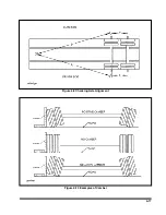
Страница 57: ...4 17 Figure 4 9 Checking Axle Alignment Figure 4 10 Examples of Camber...
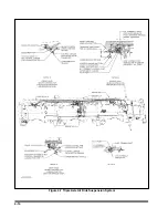
Страница 61: ...4 21 Figure 4 13 Axle and Brake Assembly...
Страница 71: ...4 31 Figure 4 21 Dock Leveler Leg Assembly...
Страница 73: ...4 33 Figure 4 22 Crank Landing Gear Assembly...
Страница 84: ...NOTES 5 10...


