


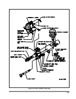


3.
Remove the existing slack adjuster and
clevis - DO NOT REMOVE EXISTING JAM
NUT.
4.
Install the new clevis (with 1/2" pin) onto
the push rod up to the jam nut -DO NOT
TIGHTEN JAM NUT.
5.
Fit the installation guide over the cam
splines so the 1/2" pin slots face the air
chamber.
6.
Swing the guide into the clevis until the
appropriate slot totally engages 1/2" pin.
7.
Observe the guide pointer arrow:
If the guide pointer is above the clevis
pointer, adjust clevis CCW for alignment.
If the guide pointer is below the clevis
pointer, adjust clevis CW for alignment.
8.
Reposition clevis until the guide pointer
aligns with the clevis pointer.
9.
Verify by engaging 1/4" pin through the
clevis and guide.
10.
Tighten jam nut to 50 ft.-lbs. torque min.
11.
Remove the guide from cam shaft.
12.
If the push rod threads extend through the
clevis more than 1/16", remove clevis and
cut rod to length.
13.
If the push rod is not fully engaged in
clevis body, install a new push rod - cut to
length.
14.
Install the slack adjuster on the cam shaft.
15.
Rotate the manual adjuster shaft CW until
the slack adjuster arm holes align with the
clevis. Install 1/2" and 1/4" pins and cotter
pins.
c. Adjusting Slack Adjuster
1.
Rotate the manual adjuster clockwise until
brake shoes contact drum.
2.
Back off manual adjuster 1/2 turn.
(counterclockwise)
3.
Manually uncage the spring brake.
4.
Build up vehicle air pressure.
5.
Fully apply and release the brakes several
times to check for adequate clearance to all
adjacent components.
6.
Measure the distance from air chamber to
1/2" pin. Apply brakes with 100-105 psi air
pressure and remeasure distance to 1/2"
pins.
7.
The stroke (difference of these two
measurements) must be less than 2 inches.
4-24
Содержание 600B Series
Страница 3: ...MODEL 600B SERIES SEMITRAILER OPERATOR S MANUAL PURCHASED FROM DATE ADDRESS PHONE NO SERIAL NO i...
Страница 8: ......
Страница 12: ......
Страница 14: ...3 2 Figure 3 1 Front Trailer Terminology Figure 3 2 Rear Trailer Terminology...
Страница 18: ...3 6 Figure 3 4 Hydraulic Controls...
Страница 26: ...3 14 Figure 3 7 Steps for Loading and Unloading...
Страница 32: ...3 20 Figure 3 10 Dock Leveler Operation...
Страница 38: ...3 26 Figure 3 14 Rear Impact Guard and Antilock Brake System...
Страница 42: ...4 2 Figure 4 1 Lubrication Points...
Страница 48: ...4 8 Figure 4 3 600B Wiring Diagram...
Страница 49: ...4 9 Figure 4 4 Remote Wiring Diagram...
Страница 52: ...4 12 Figure 4 5 Tandem Axle Air Ride Suspension System Figure 4 6 Air Ride Height Adjustment...
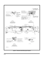
Страница 54: ...4 14 Figure 4 7 Triple Axle Air Ride Suspension System...
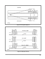
Страница 57: ...4 17 Figure 4 9 Checking Axle Alignment Figure 4 10 Examples of Camber...
Страница 61: ...4 21 Figure 4 13 Axle and Brake Assembly...
Страница 71: ...4 31 Figure 4 21 Dock Leveler Leg Assembly...
Страница 73: ...4 33 Figure 4 22 Crank Landing Gear Assembly...
Страница 84: ...NOTES 5 10...


