


CAUTION
THE AUXILIARY (BLUE) CIRCUIT IS
FOR POWERING THE SEMITRAILER
ABS. THIS CIRCUIT MUST BE HOT
WHEN THE TRACTOR KEY SWITCH IS
ON. NO OTHER ELECTRICAL DEVICES
MAY BE POWERED BY THIS CIRCUIT
WHILE THE SEMITRAILER IS MOVING
FORWARD.
Malfunction in the ABS is signaled by illumina-
tion of the ABS warning lamp located at the left
rear side of the semitrailer. The warning lamp will
come on and stay on while power is supplied to
the ABS on a moving vehicle, if there is a fault. If a
fault in the ABS exists, normal braking will still oc-
cur, but wheels may lock. The semitrailer is still op-
erable, but the system should be serviced as soon
as possible.
CAUTION
IF A FAULT EXISTS IN THE SEMI-
TRAILER ABS, NORMAL BRAKING
WILL OCCUR, BUT WHEELS MAY
LOCK. SERVICE THE ABS AS SOON
AS POSSIBLE.
The ABS is also equipped with a Blink Code
Diagnostic Tool mounted at the right rear corner of
the undercarriage or at the very rear of the trailer.
This tool is used to identify faults that may occur in
the ABS so that they may be repaired.
Refer to ABS maintenance manual supplied
with semitrailer to answer basic questions for the
anti-lock brake system, obtain outline procedures
on how to adjust, test, remove, and install ABS
components, as well as how to test for faults in the
system by using “Blink Code Diagnostics”; and il-
lustrates ABS components, wiring, and plumbing
installation diagrams.
3-24 COLD WEATHER OPERATION
3-24.1
Cold weather causes lubricants to con-
geal, insulation and rubber parts to become
hard, which may lead to problems found in
bearings, electrical systems, and air systems.
Moisture attracted by warm parts can con-
dense, collect and freeze to immobilize
equipment. The truck/semitrailer operator
must always be alert for indicators of cold
weather malfunctions.
3-24.2
During any extended stop period, nei-
ther the service nor parking brake should be
used as they can freeze up. Use wheel
chocks to secure the vehicle from moving.
3-24.3
Check all structural fasteners, air sys-
tem fittings, gaskets, seals and bearings for
looseness that can develop due to contrac-
tion with cold. Do not over-tighten.
3-24.4
Check tire inflation. Tire inflation de-
creases when the temperature decreases.
3-24.5
Periodically check drain holes in the bot-
tom of the relay valve (for trailers with air
brakes) and storage compartments. They must
be open at all times to avoid moisture en-
trapment.
3-25 HOT WEATHER OPERATION
3-25.1
Hot weather operation can create cer-
tain problems which must be checked. Ex-
pansion of parts result in tightening of bear-
ings, fasteners, and moving parts. Failure of
gaskets or seals can occur.
3-25.2
The semitrailer should be parked in the
shade if possible. Long exposure to the sun
will shorten service life of rubber components
(i.e., tires, light and hose grommets, hoses,
etc.) and paint life.
3-25.3
Check tire pressure early in the day be-
fore beginning operations while the tire is
cool. Replace all valve stem caps after
checking.
3-25.4
If the area is extremely humid, protect
electrical terminals with ignition insulation
spray. Coat paint and bare metal surfaces
with an appropriate protective sealer.
3-25.5
The use of a filter-lubricator in the tow-
ing vehicle’s air delivery system is recom-
mended.
3-28
Содержание 600B Series
Страница 3: ...MODEL 600B SERIES SEMITRAILER OPERATOR S MANUAL PURCHASED FROM DATE ADDRESS PHONE NO SERIAL NO i...
Страница 8: ......
Страница 12: ......
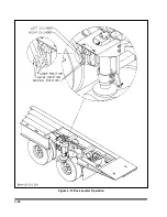
Страница 14: ...3 2 Figure 3 1 Front Trailer Terminology Figure 3 2 Rear Trailer Terminology...
Страница 18: ...3 6 Figure 3 4 Hydraulic Controls...
Страница 26: ...3 14 Figure 3 7 Steps for Loading and Unloading...
Страница 32: ...3 20 Figure 3 10 Dock Leveler Operation...
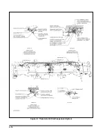
Страница 38: ...3 26 Figure 3 14 Rear Impact Guard and Antilock Brake System...
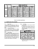
Страница 42: ...4 2 Figure 4 1 Lubrication Points...
Страница 48: ...4 8 Figure 4 3 600B Wiring Diagram...
Страница 49: ...4 9 Figure 4 4 Remote Wiring Diagram...
Страница 52: ...4 12 Figure 4 5 Tandem Axle Air Ride Suspension System Figure 4 6 Air Ride Height Adjustment...
Страница 54: ...4 14 Figure 4 7 Triple Axle Air Ride Suspension System...
Страница 57: ...4 17 Figure 4 9 Checking Axle Alignment Figure 4 10 Examples of Camber...
Страница 61: ...4 21 Figure 4 13 Axle and Brake Assembly...
Страница 71: ...4 31 Figure 4 21 Dock Leveler Leg Assembly...
Страница 73: ...4 33 Figure 4 22 Crank Landing Gear Assembly...
Страница 84: ...NOTES 5 10...


