244
8
CO/O
2
Control
With the zoom function, the scaling of the display can be enlarged and reduced.
Enlarging
1. Set the cursor to a point (20 % in this case).
2. Keep the left mouse button pressed and drag the cursor to the X-axis.
3. Release the left mouse button at the desired position.
The selected area is enlarged.
Reducing
1. Proceed in reverse order as to enlarge.
8.11
Monitoring Routines
8.11.1
Dynamic Monitoring Routines
These dynamic monitoring routines continuously check whether the probe voltage or O
2
value
has changed by more than the parametrised threshold value. If the CO controller does not de-
tect any change (dynamics) after expiration of the monitoring time, an active dynamics test is
started. This dynamics test changes the correction signal, which changes the probe signal and
the O
2
value. If the set dynamics threshold is not reached despite this, CO regulation switches
off. This fault must be reset manually.
Possible causes:
•
Parametrisation of the O
2
correctional range or CO correction range too small.
•
Parametrisation of P-term for O
2
regulation too small
•
Probe/actuator faulty
8.11.2
CO/O
2
Controller Information
O
2
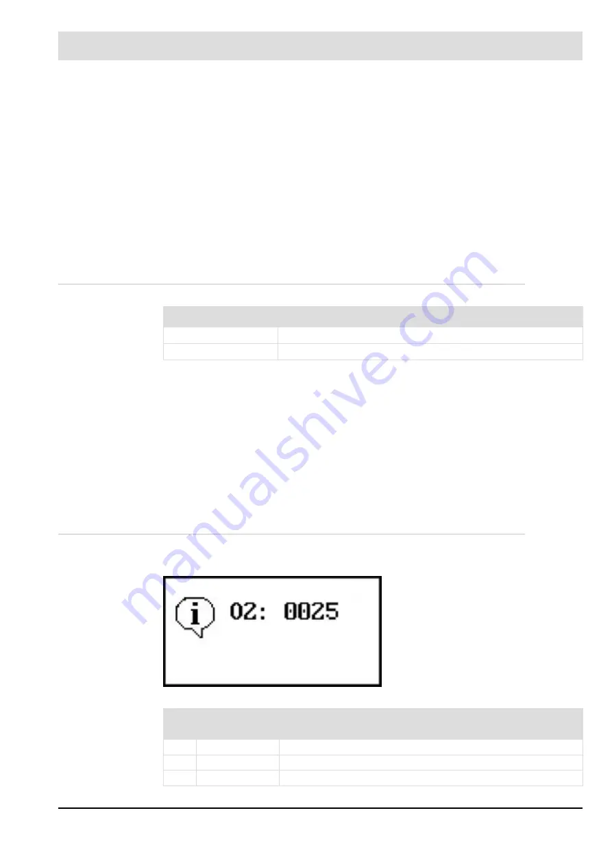
information example:
Fault display UI400
Fault description
0004
O
2
probe dynamics response
0045
CO
e
probe dynamics response
Fig. 8-38 Display of an O
2
information
O
2
trim is deactivated. Firing rate value is
outside the control range.
No.
Fault/
information
Comment
0014
O
2
information
½ air shortage: Countermeasures are inactive.
0015
O
2
information
O
2
probe dynamics missing. Increase excess air.
0016
O
2
information
Correction at stop - O
2
trim is inactive.
Содержание AEC-TPS
Страница 1: ...www lamtec de Sensors and Systems for Combustion Engineering Manual Combustion Management System CMS...
Страница 2: ......
Страница 42: ...41 4 CMS Components 4 2 5 Terminal Assignment Fig 4 9 AEC TPS 230 VAC or 120 VAC terminal assignment...
Страница 131: ...130 7 Operating Control and Displays 7 1 5 5 Deleting Curves Delete firing rate curve...
Страница 142: ...141 7 Operating Control and Displays Accessing channel information AL1 Fig 7 12 GUI6xx channel information...
Страница 148: ...147 7 Operating Control and Displays Channel configuration AL1 Fig 7 18 Channel configuration...
Страница 154: ...153 7 Operating Control and Displays Accessing the CO O2 settings AL2 Fig 7 24 CO O2 settings menu...
Страница 157: ...156 7 Operating Control and Displays Fig 7 27 System CRCs menu...
Страница 162: ...161 7 Operating Control and Displays Fig 7 32 IP setting menu...
Страница 163: ...162 7 Operating Control and Displays 7 2 8 User Settings Accessing the display settings Fig 7 33 Display settings menu...
Страница 164: ...163 7 Operating Control and Displays Accessing the language settings AL1 Fig 7 34 Language settings menu...
Страница 166: ...165 7 Operating Control and Displays Fig 7 35 Installation...
Страница 167: ...166 7 Operating Control and Displays Fig 7 36 Installation...
Страница 176: ...175 7 Operating Control and Displays Fig 7 49 Loading a protected dataset into the device...
Страница 198: ...197 7 Operating Control and Displays 1 Digital inputs 2 Digital outputs 3 PLC Signals 4 Analogue measurement values...
Страница 202: ...201 7 Operating Control and Displays Replacing a Module Fig 7 81 Module replacement menu...
Страница 271: ...270 10 Maintenance 6 Close the window Connection between PC and CMS is established Indication of the con nected CMS...
Страница 272: ...271 10 Maintenance How to update the firmware in the CMS AL2 1 Open the menu Firmware update 2 Prepare firmware update...
Страница 274: ...273 10 Maintenance Activating the Debug Data 1 Start CMS Remote Software 2 Set device online 3 Show debug data...
Страница 276: ...275 10 Maintenance 3 Restart CMS to complete the update...
Страница 282: ...281 12 Appendix 12 5 EU Declaration of Conformity...
Страница 283: ...282 12 Appendix...


