background image

16

Smart Home Control • Revision: 11-05-2016. • As of version 1.7 Subject to technical modifications and errors.

5. OPERATING THE DISPLAY
5.1. CHARGING THE BATTERY

The display has a built-in rechargeable bat-
tery which cannot be removed. The battery 
charge state is shown by the "Battery" icon:


 Charge state very good; device ready 
for operation.


 Charge state good; device ready for 
operation.


 Charge state low; charge battery.


+ audio signal every 15 minutes.


Charge state very low; charge battery.

Charge the display prior to getting started. To 
charge, connect the display via USB to a mains 
socket charger or a PC. The charger must deliv-
er a charging current of 200 mA (or more).

If the device is not charged in time, the display 
switches off. If you use a weather station with 
the system, then automatic mode is not affect-

ed by this. Automatic mode continues working 
without the interior temperature functions.

5.2. CARE AND MAINTENANCE

Fingerprints on the display and housing are 
best removed with a cloth moistened with 
water, or with a microfibre cloth. Do not use 
abrasives/cleaning agents or aggressive 
care products for cleaning.


Dispose the used battery responsi-
bly; do not dispose used batteries 
as domestic waste.

5.3.  DISPLAY AND CONTROL OPTIONS ON THE HOME 

SCREEN

The display has various areas in which in-
formation is displayed and functions can be 
accessed.

23

Betrieb des Displays

Smart Home Steuerung

 • Stand: 11.05.2016 • Technische Änderungen und Irrtümer vorbehalten.

6.

Betrieb des Displays

6.1.

Akku laden

Das Display hat einen fest integrierten Akku, der nicht entnommen werden kann. Den Ladestand
der Akkus zeigt das Symbol „Akku“:

Ladezustand sehr gut, Gerät betriebsbereit.

Ladezustand gut, Gerät betriebsbereit.

Ladezustand niedrig, Akku aufladen.

+ Tonsignal alle 15 Minuten

. Ladezustand sehr niedrig, Akku aufladen.

Laden Sie das Display vor der Inbetriebnahme auf. Zum Laden verbinden Sie das Display über USB
mit einem Netzsteckdosen-Ladegerät oder einem PC. Das Ladegerät muss einen Ladestrom von
200 mA (oder mehr) liefern.

Wenn das Gerät nicht rechtzeitig geladen wird, schaltet das Display ab. Wird eine Wetterstation im
System verwendet, dann ist die Automatik davon nicht betroffen. Die Automatik läuft ohne Innen-
temperatur-Funktionen weiter.

6.2.

Wartung und Pflege

Fingerspuren auf Display und Gehäuse entfernen Sie am besten mit einem mit Wasser befeuchte-
ten Tuch oder einem Mikrofasertuch. Zur Reinigung dürfen keine Scheuer-/Reinigungsmittel oder
aggressiven Pflegemittel verwendet werden.

Entsorgen Sie die verbrauchte Batterie bestimmungsgemäß, leere Batterien 
gehören nicht in den Hausmüll.
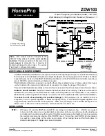
Abb. 24

Die USB-Ladebuchse befindet sich am unte-
ren Rand des Displays.

FIG. 24

The USB charging 
socket is located at 
the bottom edge of 
the display.

5. OPERATING THE DISPLAY

4.5.3  INSTRUCTIONS FOR INSTALLATION AND GET-

TING STARTED 

Do not open the terminal unit if water (e.g., 
rain) can penetrate: Just a few drops of water 
can damage the electronics.

24

Betrieb des Displays

Smart Home Steuerung

 • Stand: 11.05.2016 • Technische Änderungen und Irrtümer vorbehalten.

6.3.

Anzeige- und Bedienmöglichkeiten auf dem Startbildschirm

Das Display hat verschiedene Bereiche, in denen Informationen angezeigt und Funktionen abge-
rufen werden können. 

Daten werden geladen.

1 – Modus

Wenn eine Wetterstation angeschlossen ist, wird hier der aktuelle Modus des gewählten Ausgangs
angezeigt. 

Durch Tippen in den Bereich der Symbole (A/Hand) wird der Modus gewechselt. 
Durch langes Drücken in dem Bereich der Symbole (A/Hand) werden 

alle Ausgänge zugleich auf

Automatik geschaltet (lang drücken bis das hohe Tonsignal „langer Tastendruck“ ertönt).

Automatik-Modus. Automatikfunktionen des ausgewählten Ausgangs sind aktiv.

Manuell-Modus. Ausgang wurde manuell bedient oder in den Manuell-Modus geschaltet.

Nachdem ein Ausgang manuell bedient wurde, bleibt er im Manuell-Modus. Die Automatik

ist inaktiv. Stellen Sie einen Automatik-Reset ein, damit der Ausgang einmal täglich oder eine ge-
wisse Zeit nach einer manuellen Bedienung wieder von selbst auf Automatik schaltet (siehe Kapitel
Allgemeine Einstellungen: Automatik-Reset im Handbuch und Automatik-Reset bei den einzelnen
Automatik-Beschreibungen im Handbuch).

2 – Ladezustand des Akkus

Beachten Sie das Kapitel 

6.1. Akku laden, Seite 23.

9

 Ausgewählter Ausgang

5

 Temperatur/Wetter

8

 Wippe: Ausgang

wechseln und 
manuell bedienen

Ausgänge 

9

(Typ, Anzeigeplatz)

4

 zu den 

Einstellungen

Ladezustand

Akku 

2

3*

 Uhrzeit

Modus 

1*

Wochentag 

3*

7*

 Funktionen ausge-

wählter Ausgang

6*

 Uhrzeit-Empfang

*

 nur bei Betrieb mit Wetterstation

1* Mode

2 Rechargeable battery 
charge status

3* Time

4 Go to  

settings
5 Temperature/weather

6* Time reception

7*  Functions of 

selected output

8  Rocker: Switch  

output and  

operate manually

3* Weekday

9 Selected output

9  Outputs (type, 

display slot)

* Only for operation with weather station

Loading data

Содержание Smart Home

Страница 1: ... SMART HOME CONTROL PACKAGE OPERATING MANUAL Serving the customer is our first priority Customized Intelligence ...

Страница 2: ...tware version please check the Downloads menu section on www lamilux com to see if a recent version of the manual is available EXPLANATION OF SYMBOLS Safety information Safety instructions for work ing on electrical connections components etc DANGER indicates an imminently hazardous situation that will result in death or serious in jury if not avoided WARNING indicates an imminently hazardous situ...

Страница 3: ...ing the battery 5 2 Care and maintenance 5 3 Display and control options on the home screen 5 3 1 Meaning of function icons automatic status 5 4 Audio signals 5 5 Error messages 5 6 Table memory capacity of outputs and inputs 6 GETTING STARTED PAGE 24 6 1 Short setup 7 OPERATING THE WEATHER STATION PAGE 28 7 1 Maintenance of the weather station 8 WLAN MODULE PAGE 28 8 1 Description 8 1 1 Scope of ...

Страница 4: ...ng control switches lamps to reflect the outside lighting con ditions day night and time If dimming modules are used then the dimming lev el brightness of the lamp is considered The heating control system actuates a one or two stage heating system as a function of the indoor temperature tak ing into account day and night timer it has a timer switch for manual heating during night operation Automat...

Страница 5: ...ses for shading window drives A group control relay can be used to connect several drives to one RF MSG if needed Switching Relay RF Relay ST RF Re lay UP both as of version 5 5 for con sumers such as lights and single stage heating Dimmers RF L UN ST RF L LED ST as of version 1 4 in each case RF L UP 1 10 V as of version 1 1 for dimmable lamps Heating module RF HE ST as of version 5 for two stage...

Страница 6: ...mperature Operation 0 50 C Storage 10 50 C Ambient humidity max 95 rF Avoid condensation Operating voltage 3 8 V rechargeable battery USB charging current 100 mA Radio frequency 868 2 MHz Temperature measuring range 40 C 80 C Housing Composite Colour Grey Installation Surface mount Degree of protec tion IP20 Dimensions approx 201 x 75 x 121 W x H x D mm Weight Approx 610 g Ambient temperature Oper...

Страница 7: ...x D mm Weight Approx 80 g Ambient temperature Operation 30 50 C Stor age 30 70 C Voltage 24 V DC Current max 105 mA Measuring range 30 C 50 C Resolution 0 1 C Accuracy 0 5 C at 30 C 25 C 1 5 C at 30 C 45 C Measuring range 0 m s 35 m s Resolution 0 1 m s Accuracy 15 of the measured value with an incident flow of 45 to 315 frontal incident flow corresponds to 180 Measuring range 0 Lux 150 000 Lux Re...

Страница 8: ...ed as a sta tionary system that is only in mounted con dition following completion of all installation and commissioning work and only in the intended environment Lamilux is not liable for changes in standards after publication of the operating manual 4 2 NOTES ON WIRELESS EQUIPMENT When planning systems with devices that use wireless communication methods at tention must be paid to sufficient wir...

Страница 9: ...for detaching the cover should face downward so that it is as unobtrusive as possible 10 Installation Montage Smart Home Steuerung Stand 11 05 2016 Technische Änderungen und Irrtümer vorbehalten Abb 1 Lösen Sie die Abdeckung von der Wandbe festigung Lösen im nicht montierten Zustand Ausliefe rungszustand Trennen Sie die beiden Teile indem Sie die Abdeckung außen festhalten und mit den Daumen die W...

Страница 10: ... die Temperaturmessung kann durch äußere Einflüsse verfälscht werden z B durch Erwär mung oder Abkühlung des Baukörpers an dem der Sensor montiert ist Sonneneinstrahlung Hei zungs oder Kaltwasserrohre Abb 5 Lösen der Abdeckung im montierten Zustand Hebeln Sie vorsichtig mit einem kleinen Schraubendreher in die Kerbe Nehmen Sie die Abdeckung ab FIG 6 The device must have at least 60 cm clear ance t...

Страница 11: ...4 Installation Montage 4 4 2 Aufbau des Geräts ACHTUNG Schon wenige Tropfen Wasser können die Elektronik des Geräts beschädigen Öffnen Sie das Gerät nicht wenn Wasser z B Regen eindringen kann Abb 10 1 GPS Empfänger im Deckel 2 Helligkeitsmessung 3 Niederschlagssensor im Deckel 4 Temperaturmessung 5 Windmessung ACHTUNG Empfindlicher Windsensor Transportschutz Aufkleber nach der Montage entfernen D...

Страница 12: ...rung aus Führen Sie das Anschlusskabel durch die Gummi dichtung Kabeldurchführung Gummi dichtung 15 Installation Montage Smart Home Steuerung Stand 11 05 2016 Technische Änderungen und Irrtümer vorbehalten 4 4 3 Montagevorbereitung 4 4 4 Anbringen des Unterteils mit Halterung Montieren Sie nun zunächst das Gehäuseunterteil mit der integrierten Halterung für die Wand oder Mastmontage Wandmontage Ve...

Страница 13: ...n FIG 21 Screw the cover top and lower part bottom together 18 Installation Montage Smart Home Steuerung Stand 11 05 2016 Technische Änderungen und Irrtümer vorbehalten 4 4 6 Montage abschließen 4 4 7 Hinweise zur Montage und Inbetriebnahme Öffnen Sie die Wetterstation nicht wenn Wasser Regen eindringen kann Schon wenige Tropfen könnten die Elektronik beschädigen Entfernen Sie nach der Montage all...

Страница 14: ... damage caused by incorrect wiring Incorrect wiring can cause permanent dam age to the device or electronic devices con nected to it Note the labelling of the connection ter minals and connect the mains supply weather station drives and equipment at the intended positions only NOTES ON TEACHING IN WIRELESS CONNECTIONS Teaching of wireless nodes at the terminal unit is facilitated by protecting the...

Страница 15: ...unit operation Weather data Flashes on receiving a data packet Status Programming LED 5 Programming button for teaching wireless connections 6 Fine fuse 6 3 AT for 230 V motor 1 2 no 10 11 7 Fine fuse 6 3 AT for dimmer no 9 8 Mains voltage connection 230 V AC 50 Hz 9 LED Strip Powerbox connection accessory 10 Motor connection 1 230 V AC 11 Motor connection 2 230 V AC 12 Fastening tabs 21 Inbetrieb...

Страница 16: ...as Gerät nicht rechtzeitig geladen wird schaltet das Display ab Wird eine Wetterstation im System verwendet dann ist die Automatik davon nicht betroffen Die Automatik läuft ohne Innen temperatur Funktionen weiter 6 2 Wartung und Pflege Fingerspuren auf Display und Gehäuse entfernen Sie am besten mit einem mit Wasser befeuchte ten Tuch oder einem Mikrofasertuch Zur Reinigung dürfen keine Scheuer Re...

Страница 17: ...the outdoor weather data In this case you can toggle between the Temperature and Brightness Wind displays by tapping the area with the values 25 3 Uhrzeit Wochentag nur bei Betrieb mit Wetterstation Die Uhrzeit kann nach 12 oder nach 24 Stunden Schema dargestellt werd nen zum Stellen der Uhr finden Sie im Kapitel Uhrzeit einstellen im Handbu 4 Einstellungsmenüs Kurz drücken um in die Automatik Ein...

Страница 18: ...ttom of the screen with the display slot number and type icon The selected output is indicated by a box around the display slot number Note that at this point only those outputs are displayed for which the displays has been enabled see manual section Display slot in the descriptions of the basic settings for motorised control units RF MSG weather station for relays RF relay RF HE and for dimmers R...

Страница 19: ...ing is released If the icon is not displayed the outdoor temperature lock is active Retraction delay running Shading has been locked due to low indoor temperature Sun direction Sun in shade area compass direction Shading is released Solar protection function Brightness threshold for shading ex ceeded extend delay running Shad ing is extended after the delay time if all other conditions are OK Brig...

Страница 20: ...OK Ventila tion is released If the icon is not dis played the outdoor temperature lock is active Ventilation function Indoor temperature for ventilation ex ceeded Ventilation is performed if all other conditions are OK LIGHT A detailed description of the automatic mode functions can be found in the Auto matic lighting section of the manual Value dropped below dusk threshold Light is switched on af...

Страница 21: ...NALS If a button or a touch sensitive area is actuat ed a short audio signal can be heard If ER Error is displayed instead of a sensor value then the connection to a connected weather station is inter rupted or the sensor is defective Check whether the weather station still has a voltage supply fuse If the problem per sists call in a qualified electrician to check the device Installation checking ...

Страница 22: ...22 Smart Home Control Revision 11 05 2016 As of version 1 7 Subject to technical modifications and errors Storage slot Type Display slot Room Keyword ...

Страница 23: ...ngen 2 Zum Bereich LER Lernen wechseln 3 Den Bereich LER anwählen 4 Drücken Sie kurz auf das Wetterstations Symbol Die Lernbereitschaft wird durch die Ani mation des Antennen Symbols angezeigt 5 Schalten Sie die Spannungsversorgung der Anschluss Einheit ein 16A Automat im Verteiler Si cherungskasten oder drücken Sie die PRG Taste im Gehäuseinnern WARNUNG Elektrische Spannung Die Programmier Taste ...

Страница 24: ...Ab um herauszufinden welcher Motor oder Verbraucher den Speicherplatz belegt Notieren Sie die Funktion in der 2 1 6 Tabelle Spei cherplätze der Aus und Eingänge Seite 32 ACHTUNG Regen und Windalarm sind deaktiviert solange die Grundeinstellungen angezeigt werden Bei jedem Ausgang können Sie die Einstellungen nach einander vornehmen oder Punkte über springen um zur gewünschten Einstellung zu gelang...

Страница 25: ... wird Sie können dazu den Antrieb mit den Auf Ab Tasten bewegen ACHTUNG Regen und Windalarm sind deaktiviert solange dieser Menüpunkt angezeigt wird Wählen Sie EINF Einfahren wenn die Beschattung mit der Taste AUF einfährt Wählen Sie AUSF Ausfahren wenn die Beschattung mit der Taste AUF ausfährt Der Wert blinkt und wird in diesem Menü ausnahmsweise mit Rechts Links geändert 5 6 7 Ausgänge Speicher...

Страница 26: ...l Save long Check status up down Back to Home screen Setting Extend time Value Change value Up Down Back without saving Type and display slot home screen 60 Ausgänge einrichten Smart Home Steuerung Stand 11 05 2016 Technische Änderungen und Irrtümer vorbehalten 5 Die Einstellung des Ausgangs Speicherplatzes anwählen 6 Zur Einstellung AUSF Ausfahrzeit wechseln 7 Die Einstellung AUSF anwählen Passen...

Страница 27: ...und stellen Sie sie hier ein Beschattungen Markise Jalousie Rollladen Ermitteln Sie die Fahrzeit für das Einfahren das heißt wie lange der Antrieb benötigt um von der komplett ausgefahrenen Stellung Beschattung 100 bis zur komplett eingefahrenen Stellung si chere Position zu fahren 5 Die Einstellung des Ausgangs Speicherplatzes anwählen Zurück ohne Speichern Einstellung Öffnungs fahrzeit Speichern...

Страница 28: ...an impair the sensor function ATTENTION The device may be damaged if water enters the housing Do not clean with pressure cleaners or steam jets 8 1 DESCRIPTION The WiFi module connects the smart home control with the Lamilux Smart Home App Devices and drives can be operated manually with the app installed on your mobile device Measured values from sensors inside the system and the weather station ...

Страница 29: ...n of the operating manual 8 2 2 REQUIREMENTS To be able to use the WiFi module the following criteria must be fulfilled You must have a mobile device smart phone or tablet with the Android oper ating system 4 0 3 Apple iOS 8 0 or higher A Smart Home Control must be set up A router and a configured wireless net work WLAN must be available Se cure your WLAN against unauthorised access by taking appr...

Страница 30: ...t the side 4 Einrichtung von Modul WLAN App WLAN Modul Stand 01 06 2016 Technische Änderungen und Irrtümer vorbehalten Für iPhone iPad Öffnen Sie den Appstore und Installieren Sie die App Lamilux Smart Home 3 2 WLAN Modul in Betrieb nehmen Das Modul wird in eine Netzsteckdose CEE 7 4 gesteckt Die Netzspannung muss 230 V AC 50 Hz betragen Über die Anzeigeart der Status LED an der Seite kann der akt...

Страница 31: ... Home App LED flash es regularly at short intervals Connected to router The WiFi module is now connected to your router Connect your mobile device to the same wireless network and launch the app LED goes out briefly every 2 seconds No WiFi connection to router Connection could not be estab lished to your router You may need to move the WiFi module closer to the router If you changed your router s ...

Страница 32: ... seconds 8 4 USING THE APP The app has two sections Overview and Op erations 8 4 1 OVERVIEW FIG 28 Screenshot Overview page This shows you a list of all the occupied slots on the Smart Home Control The correspond ing slot is selected by tapping and the view changes to the Operations page You can additionally change the display name in the app CHANGING THE NAME IN IOS Click Edit in the top left Tap...

Страница 33: ...tigen Sie entweder mit OK oder schließen sie das Eingabefenster mit Abbrechen Namen ändern in Android Halten Sie die gewünschte Postion so lange gedrückt bis ein Textfeld mit Tastatur erscheint Bestätigen Sie mit OK oder berühren Sie das Display außerhalb des Tastaturbereichs um abzubrechen 4 2 Bedienungs und Anzeigeseite der App Wechseln Sie zur nächsten vorherigen Position indem Sie in der obere...

Страница 34: ...rmöglichen sollten die Anschluss Einheit separat abgesichert sein 16A Automat Weitere Funk Teilnehmer sollten über andere Automaten versorgt werden Da durch kann die Spannungsversorgung der Anschluss Einheit und der anderen Funkteilneh mer unabhängig von einander unterbrochen werden 4 5 2 Übersicht Anschlüsse Abb 22 Anschlussplätze der An schluss Einheit nicht Wetterstation Antrieb Antrieb Antrieb...

Страница 35: ...11 05 2016 As of version 1 7 Subject to technical modifications and errors 10 CONNECTOR VOLTAGE SUPPLY SUPPLY CABLE MOTOR 230 V L PE N N PE L1 L2 VOLTAGE SUPPLY SUPPLY CABLE MOTOR 24 V Connection is polarity independent WIRE 2 WIRE 1 ...

Страница 36: ... the vector between the outer surfaces of the material Functional values refer to test specimens and the dimensions used in testing only We cannot provide any further guarantees of technical values This particularly applies to changes in installation locations or if dimensions are re measured on site LAMILUX Heinrich Strunz GmbH Zehstraße 2 PO Box 1540 95111 Rehau Germany Tel 49 0 92 83 5 95 0 Fax...

Отзывы: