52
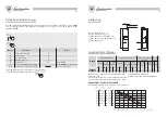
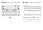
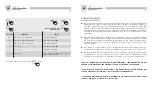
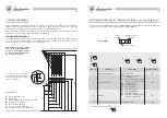
When leaving the factory the burners are set to operate with NATURAL GAS. For the calibration see the
table below:
BURNER PRESSURE CURVE - OUTPUT
GAS - NOZZLE CALIBRATION
∆
P Servo = pressure jump measured between points upstream and downstream of nozzle.
∆
P Servo
Delivery
Burner
nozzle
min.
max.
m
3
/h
Gas type
NATURAL GAS
(G20-20mbar)
0,7
5,7
2,64
Hi
kcal/m
3
8.120 *
∗
= at 1013 mbars, 15
°
C.
Ø mm.
5,8
CO
2
%
min.
max.
8,8
9
NOx
Class
5
53
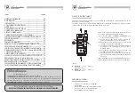
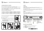
HEATING WITH OUTDOOR SENSOR AND ROOM THERMOSTAT
For proper use of the outdoor sensor it is compulsory to fit the room thermostat which adjusts delivery
temperature T1 to ambient conditions.
For each outdoor temperature reading between T4 (via parameter n
°
6, adjustable between –20
°
C and
+10
°
C) and 30
°
C there corresponds a delivery temperature T1 between the T1 temperature set by the
user on the boiler (phase. n
°
4) and the minimum operating temperature fixed at 55
°
C (see boiler
operation curve).
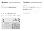
The graph-illustrated example shows T4 set to -10
°
C and delivery temperature set to 75
°
C. If, for
example, the outdoor sensor detects a temperature of –5
°
C and the room thermostat is requesting heat
(contact closed) the boiler will “try” to reach a delivery temperature of 65
°
C. If the room thermostat
continues requesting heat the delivery temperature increases by 10
°
C every ten minutes. Vice versa, if
the thermostat contact opens the delivery temperature falls by 1
°
C each elapsed minute. The chapter
“PARAMETER DISPLAY AND MODIFICATION” (page 48) shows admissible parameter values regarding
outdoor sensor operation. The values must be adjusted as follows:
Phase n
°
5
T1 heating minimum temperature adjustable between 15
°
C and 25
°
C.
6
T4 minimum outdoor temperature range -20
°
C to +10
°
C (adjusted on the basis of minimum design
temperature).
b
BOILER TYPE: adjusted to 00 (fixed): adjustment valid for installation of room temperature thermostat
with outdoor sensor.
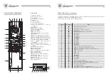
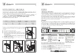
BOILER OPERATION CURVE


