BT900-Sx Hardware Integration Guide
Intelligent BTv4.0 Dual Mode Module
Embedded Wireless Solutions Support Center:
http://ews-support.lairdtech.com
www.lairdtech.com/bluetooth
37
Americas: +1-800-492-2320
Europe: +44-1628-858-940
Hong Kong: +852 2923 0610
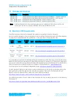
Table 18: Recommended Maximum and minimum temperatures
Specification
Value
Unit
Temperature Inc./Dec. Rate (max)
1~3
°C / Sec
Temperature Decrease rate (goal)
2-4
°C / Sec
Soak Temp Increase rate (goal)
.5 - 1
°C / Sec
Flux Soak Period (Min)
70
Sec
Flux Soak Period (Max)
120
Sec
Flux Soak Temp (Min)
150
°C
Flux Soak Temp (max)
190
°C
Time Above Liquidous (max)
70
Sec
Time Above Liquidous (min)
50
Sec
Time In Target Reflow Range (goal)
30
Sec
Time At Absolute Peak (max)
5
Sec
Liquidous Temperature (SAC305)
218
°C
Lower Target Reflow Temperature
240
°C
Upper Target Reflow Temperature
250
°C
Absolute Peak Temperature
260
°C
9
FCC
AND
IC
R
EGULATORY
S
TATEMENTS
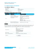
Model
US/FCC
CANADA/IC
BT900-SA
SQGBT900
SQGBT900
BT900-SC
3147A-BT900
3147A-BT900
The BT900-SA and BT900-SC hold full modular approvals. The OEM must follow the regulatory guidelines
and warnings listed below to inherit the modular approval.
PART #
FORM FACTOR
TX OUTPUT
ANTENNA
BT900-SA-0X
Surface Mount
8 dBm
Ceramic
BT900-SC-0X
Surface Mount
8 dBm
u.FL
*Last two slots "0X" in Part # are used for production firmware release changes. Can be values 01-99, aa-
zz
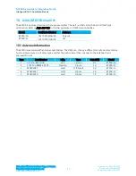
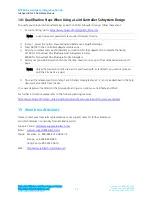
The BT900 family has been designed to operate with the antennas listed below with a maximum gain of
2.0
dBi. The required antenna impedance is 50 ohms.
Item
Part Number
Mfg.
Type
Gain (dBi)
Model
1
AT3216-B2R7HAA
ACX
Ceramic
0.5
BT900-SA
2
S181FL-L-RMM-2450S
Nearson
Dipole
2.0
BT900-SC
3
MAF94045
Laird
PCB Dipole
2.0
BT900-SC
4
MAF94017
Laird
Dipole
2.0
BT900-SC
5
MAF94019
Laird
Dipole
1.5
BT900-SC
Note: The OEM is free to choose another vendor’s antenna of like type and equal or lesser gain as an
antenna appearing in the table and still maintain compliance. Reference FCC Part 15.204(c)(4) for
further information on this topic.
To reduce potential radio interference to other users, the antenna type and gain should be chosen
so that the equivalent isotropic radiated power (EIRP) is not more than that permitted for
successful communication.


