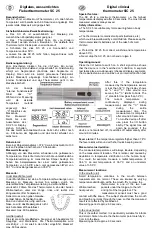
Explanation of the operating elements
Operation
12
Electrical connection Controller
Safety extra-low voltage
13-16 CAN BUS
17+18 Sensor for HS2
(= Boiler 2) KF2
alternatively:
19+20 Return flow
sensor VF
only in the case of return
flow temperature
increase
22+23 Sensor for HS1
(Boiler1) KF1
24+25 Outdoor sensor
(frost protection only)
E
Attention: For the connection (230 V) fixed or flexible
lines with the factory-standard lead end sleeves are to
be installed.
E
The controller is designed for an operating voltage of
230 V AC at 50 Hz. The burner contact is a floating
contact and must always be connected in series with
the mechanical boiler thermostat.
230V
∼
; Relay switching capacity 2(2)A, 250V
∼
1+2 Burner 1 (floating contact)
5 Mixer OPEN /
HS2 pump
6 Mixer CLOSE /
Return flow temperature increase
pump
7 Pump heating circuit / HS /
Collector
8 L1´Power supply, relay
9 Power supply, device
10 N-conductor, mains
11+12 Burner 2 / Stage2 (floating
contact); Potential for example with
bridge 11 to 9
E
Attention: Bus lines and sensor lines are to be installed
separately from supply lines!
!
Switches 1-5 are always without function in this
version. Switch 6 must be used to set the sensor type!


