background image

HUMMEL

®

  01.01.2019

English / Englisch

4.3   SWITCHING ON THE MACHINE

  CAUTION!

RISK OF INJURY and RISK OF PROPERTY DAMAGE from 

rotating parts of the machine:

•   Always tension the sanding belt before switch on the 

machine (fig. 18)!

•   Always lift the sanding drum off the floor before switch 

on the machine (fig. 19)! 

•   Never allow the machine to run unattended!

4.3.1  MACHINES WITH SINGLE-PHASE AC MOTOR 

(MAINS VOLTAGE 230 V AND 220 V)

1


Lift the sanding drum off the floor by turning the lowering 
lever at the handle upwards (fig. 19)!

2


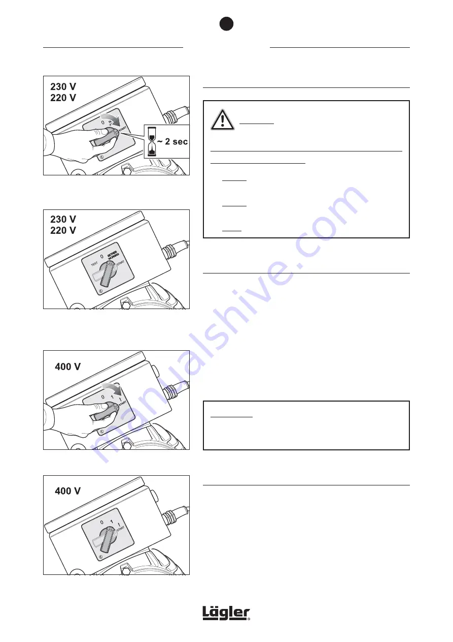
To switch on the machine turn the switch button at the motor 

to position -START- and hold the switch button for around 

2 seconds in this position (fig. 23). 

3


Once the motor has reached its full speed, release the switch 

button. The switch button will then automatically move to 

position -BETRIEB (WORKING)- (fig. 24).

ATTENTION!

Remaining for too long in the switch position -START- 
shortens the service life of the starting capacitor! 

4.3.2  MACHINES WITH THREE-PHASE AC MOTOR 

(MAINS VOLTAGE 400 V)

1


Lift the sanding drum off the floor by turning the lowering 
lever at the handle upwards (fig. 19)!

2


To switch on the machine turn the switch button at the motor 

to position -START- (fig. 25) and release the switch button 

after the motor has reached its full speed. The switch button 

will then automatically move to position -1- (fig. 26). 

COMMISSIONING

Fig. 23 

To switch on the machine turn the switch button at 
the motor to position -START- and hold the switch 
button for around 2 seconds in this position.

Fig. 24 

Once the motor has reached its full speed, 
release the switch button. The switch button will 
then automatically move to position -BETRIEB 
(WORKING)-.

Fig. 26 

Release  the  switch button. The button turns 
automatically in position -1-.

Fig. 25 

To switch on the machine turn the switch button 
at the motor to position -START-.

4

22

Содержание HUMMEL

Страница 1: ...T SANDING MACHINE HUMMEL English Englisch HUMMEL www laegler com 00 100 20 002 01 01 2019 00 100 20 002 Operating Instructions Translation of original operating instructions for the belt sanding machi...

Страница 2: ...pe plate 14 3 1 2 Motor type plate 15 3 2 Machine data 16 4 Commissioning 18 4 1 Preparing the machine for operation 18 4 2 Connecting the power cable 21 4 3 Switching on the machine 22 4 3 1 Machines...

Страница 3: ...enance work in accordance with accident prevention regulations 57 9 Causes of faults 59 9 1 The machine does not run or has switched off automatically 59 9 2 The machine attempts to start up but is no...

Страница 4: ...chine HUMMEL Cable support with strain relief ring ON OFF switch Switch box Lowering lever Handle Guide tube Safety guard Side cover Lateral wheel Drive motor Belt guard Bumper felt Operating lever dr...

Страница 5: ...cables and dust bag are attached 1 3 INTENDED USE OF THE MACHINE The HUMMEL belt sanding machine is suitable for dry sanding wooden and cork floors plastic skating rinks and tartan running tracks A sp...

Страница 6: ...for operation 1 Operating instructions 1 Dust bag 1 MultiClip for dust bag fixture 1 Cable support 1 O ring as a strain relief device 1 Extension cable length 10 m 394 for single phase AC motor 3 x 2...

Страница 7: ...and the safety related parts mentioned below at regular intervals in order to be able to work safely and optimally at all times Replace the following parts in case of wear and or damage Extension cabl...

Страница 8: ...nt must be conducted by a qualified expert for safety reasons The machine must be switched off and the power plug must be removed from the socket during all maintenance work and all work on the electr...

Страница 9: ...hten the screws There is a high risk of fire when sanding woods with a large amount of resin oiled or waxed floors or metal Therefore the machine must always be cleaned carefully directly after sandin...

Страница 10: ...the mains supply must not exceed 20 m 790 HEALTH RISK caused by dust Make sure that the dust bag is properly fastened to the machine Do not use damaged washed or repaired dust bags Do not work with a...

Страница 11: ...l machine unattended Do not reach into rotating tools or parts of the machine Do not wear any long articles of clothing or jewelry These could be caught by moving parts RISK OF INJURY and RISK OF PROP...

Страница 12: ...es you must inspect the safety devices carefully to ensure that they are working perfectly and as intended Check whether the moving parts are working properly that they are not sticking that no parts...

Страница 13: ...ea tidy Untidy work areas create a risk of accidents Use the proper machines Do not use low performance machines or additional devices for heavy jobs Do not use the machine for purposes and work that...

Страница 14: ...sioner fig 3 The following technical data are specified on the machine type plate fig 4 1 Manufacturer 2 Serial number of machine Mach No 3 Year of manufacture Year 4 Machine name Type 5 Weight of mac...

Страница 15: ...CPS Hz 8 Motor power in kilowatt KW 9 Motor speed in 1 min Rpm 10 Power factor cos phi cos 11 Insulation class Insul Cl 12 Protection class Prot Cl 13 Type of current 14 Country of manufacture Fig 6...

Страница 16: ...or 40 F 40 F Motor type three phase AC motor Voltage 400 V Frequency 50 Hz CPS Motor power 4 0 kW Necessary fuse protection of mains supply at least 16 A Insulation class B Protection class IP 54 Safe...

Страница 17: ...le workplace values may also vary from country to country This information however is intended to enable the user to better estimate the dangers and risks Overall length of machine 1040 mm approx 40 9...

Страница 18: ...ainer for storage or transportation of the machine Section 6 Transport and storage Please ensure that the packaging materials are responsibly disposed of 2 Press the lowering lever at the handle downw...

Страница 19: ...the tensioning roller 10 Position the sanding belt on the tensioning roller of the drive unit fig 15 and push it over the tensioning roller and the sanding drum fig 16 Fig 12 Hook the cable support in...

Страница 20: ...tion 7 3 Checking and setting the sanding belt tracking CAUTION RISK OF INJURY and RISK OF PROPERTY DAMAGE from rotating parts of the machine Always tension the sanding belt before switch on the machi...

Страница 21: ...V or 230 V Cables with three wires and wire cross sections of at least 2 5 mm 0 0039 sq in Machines with motor for mains voltage 400 V Cables with five wires and wire cross sections of at least 1 5 m...

Страница 22: ...ORKING fig 24 ATTENTION Remaining for too long in the switch position START shortens the service life of the starting capacitor 4 3 2 MACHINES WITH THREE PHASE AC MOTOR MAINS VOLTAGE 400 V 1 Lift the...

Страница 23: ...cable fig 29 1 To unlock the phase changing switch turn the screwdriver 180 against a small resistance fig 29 2 ATTENTION The phase changing switch can only be turned in one direction 4 3 3 GENERAL I...

Страница 24: ...from the socket after you have switched off the machine Secure the machine against sliding For example place a flat piece of wood between the floor surface and machine housing fig 32 ATTENTION Do not...

Страница 25: ...s made by previously used grit grade by adhering to the order of the sandpaper grit grade and never skip more than one grit grade Vacuum the floor thoroughly always directly before each workstep every...

Страница 26: ...the sanding pressure should be reduced and the sanding speed increased 5 3 CHANGING THE SANDING BELT Depending on the type of sanding process you wish to perform different abrasive grit grades can be...

Страница 27: ...drum fig 39 A WARNING RISK OF FIRE from the formation of sparks while sanding Position B of the sanding belt in fig 39 provoke sparking during sanding Avoid this without fail Fig 39 Position the sand...

Страница 28: ...and setting the sanding belt tracking CAUTION RISK OF INJURY and RISK OF PROPERTY DAMAGE from rotating parts of the machine Always tension the sanding belt before switch on the machine fig 40 Always...

Страница 29: ...ld levels please note The dust bag must be emptied when it is one third full at the very latest in order to prevent a deterioration of the suction performance due to the lack of filtering surface area...

Страница 30: ...Empty the dust bag into a non combustible container outdoors Cover this container with a non combustible cover and be certain to store it and the dust bag outdoors in non combustible environment RISK...

Страница 31: ...hout dust bag Store the used dust bag in a closed non combustible container ATTENTION During transport or storage place a flat piece of wood between the floor surface and machine housing fig 44 This p...

Страница 32: ...r bearing bracket fig 47 The motor nut must only be backed out from the fitting between the motor nut and motor bearing bracket and not completely removed fig 48 5 Open the belt guard fig 49 6 Release...

Страница 33: ...n the lower pulley and allow the drive V belt to run off the lower pulley fig 52 If necessary use the box wrench see tool kit to turn the lower pulley exclusively clockwise ATTENTION Only turn the nut...

Страница 34: ...e housing fig 55 3 ATTENTION Do not tighten the wing nut at the machine housing while the guide tube is removed fig 56 Otherwise the machine housing could break Fig 55 After opening the wing screw 1 a...

Страница 35: ...MEL after transport adhere to the following sequence of work steps 1 Press the lowering lever at the handle downwards fig 57 1 2 Insert the guide tube into the opening in the machine housing and at th...

Страница 36: ...ansport and store the machine without dust bag Store the emptied dust bag in a closed non combustible container If you wish to keep the machine in storage for a protracted period ensure that it is kep...

Страница 37: ...bers in Section 11 Spare parts HUMMEL This is the only way to ensure that your machine continues to perform Warranty claims for foreign parts or damage caused thereby cannot be accepted Never conduct...

Страница 38: ...notethewarningnoticesofthemanufacturers of the paint oil and wax RISK OF PROPERTY DAMAGE Never use any cleaning products which contain solvents 7 1 1 GENERAL Before starting work you should perform th...

Страница 39: ...d using the following procedure 1 Lift the sanding drum off the floor by turning the lowering lever at the handle upwards fig 65 2 Switch off the machine and pull the power plug out of the socket 3 Re...

Страница 40: ...Guide rollers which are not rotatable easily provoke sparking during sanding and must be replaced without fail part number in Section 11 Spare parts HUMMEL 10 Reassemble in reverse order 11 After moun...

Страница 41: ...linkage at the lever plate B Lever plate on the handle shaft To do this tilt the machine slightly to one side and allow a small amount of oil to run into the lubrication points C Wing screw on the bo...

Страница 42: ...o objects randomly positioned in the vicinity can be picked up by the sanding belt and no other persons are in the danger area 4 Machines with single phase AC motor mains voltage 230 V and 220 V Turn...

Страница 43: ...ve unit and the sanding belt tracking must be checked again Section 7 3 1 Checking the sanding belt tracking 5 Always set the sanding belt tracking using a sanding belt with as fine a grit grade as po...

Страница 44: ...INJURY and RISK OF PROPERTY DAMAGE from rotating parts of the machine If the lock nut at the upper part of the drive unit is not tightened it will loosen during operation of the machine and falls on...

Страница 45: ...ckwards over the safety guards so that you can see the wheel bearings fig 81 Ensure that the machine is standing securely 4 The wheel on the belt guard side can be adjusted by releasing the tension sc...

Страница 46: ...ty and that of others the following points must be observed Always used original L GLER dust bags part number in Section 11 Spare parts HUMMEL Never use damaged washed patched or in any other way repa...

Страница 47: ...ary take a soft hammer to help you loosen the nut Never use a steel hammer 8 Turn the sanding drum in such a way that the groove is pointing upwards to ensure that the parallel key is not lost fig 88...

Страница 48: ...not use any cleaning products which contain solvents 6 Insert the compression spring and the tensioning roller Ensure that the surfaces on the shaft ends of the tensioning roller are pointing upwards...

Страница 49: ...he machine and fall on rotating parts ATTENTION If the lock nuts of the fixing screws are not tightened the tensioning roller can move out of place This cause negative effects to the sanding result 10...

Страница 50: ...elease the screw in the center of the wheel and remove the screw washers and nut fig 97 Ensure that you do not lose the nut 5 Pull the back wheel off the tail axle housing 6 Push the new back wheel on...

Страница 51: ...se the screw which fastens the tail axle of the rear wheel in the machine housing fig 98 5 Pull the complete rear wheel assembly out of the machine housing fig 98 6 Mount the complete new back wheel i...

Страница 52: ...100 Before removing the left lateral wheel open the belt guard fig 101 5 Pull the wheel off the wheel lever 6 Push the new wheel onto the wheel lever 7 Mount the washers and the screw 8 Tighten the sc...

Страница 53: ...y turning the eye bolt at the motor counterclockwise fig 104 6 Open the clamping screw of the belt tensioner for the suction V belt fig 105 1 7 Turn the belt tensioner clockwise to release the tension...

Страница 54: ...f the belt tensioner for the suction V belt fig 105 1 2 Turn the belt tensioner clockwise to release the tension of the suction V belt fig 105 2 3 Loosen the two nuts at the eye bolt at the motor fig...

Страница 55: ...n the clamping screw at the belt tensioner carefully at the same time fig 113 2 Correct tension of the suction V belt The slack on the V belt should be approx 1 cm 0 4 if compressed with normal effort...

Страница 56: ...ghten the two motor nuts fig 115 8 Close the belt guard fig 116 ATTENTION Never tension the V belts excessively This can cause damage to the V belts and ball bearings Check the tension of the V belts...

Страница 57: ...red The functional efficiency must also be confirmed Ensure that only original L GLER spare parts are used for mainte nance work You should only allow the customer service work to be conducted by L GL...

Страница 58: ...s used extension and device connection cables with plugs connection cables with plugs movable cables with plugs and fixed connections Inspection interval Every 6 months as a reference value 3 months o...

Страница 59: ...e switch in the motor has switched off the machine because the power cables have a total length of more than 20 m 790 the power cables have wire cross sections which are too small at mains voltage 220...

Страница 60: ...connection The power cables have a total length of more than 20 m 790 The power cables have wire cross sections which are too small at mains voltage 220 V or 230 V are the wire cross sections smaller...

Страница 61: ...ions which are too small at mains voltage 220 V or 230 V are the wire cross sections smaller than 2 5 mm 0 0039 sq in at mains voltage 400 V are the wire cross sections smaller than 1 5 mm 0 0023 sq i...

Страница 62: ...worn out and must be replaced Section 7 10 Replacement and tensioning of V belts A pulley is dirty damaged or worn out and must be cleaned or replaced There are clogged materials and deposits in the m...

Страница 63: ...corrected Section 5 2 Regulating the sanding drum pressure The machine setting is incorrect and must be adjusted The sanding drum must sands centrally Section 7 4 Checking the machine setting The san...

Страница 64: ...he sanding drum while sanding The following causes must be eliminated additional weight is on the machine the rear part of the machine is lifted on with the handle while sanding the lowering lever at...

Страница 65: ...HUMMEL 01 01 2019 English Englisch NOTES 65...

Страница 66: ...gler com C tarting capacitor A S C unning capacitor B R Ha ain winding M Hi uxiliary winding A R1 esistor R K1M ontactor C Mains supply 230 V 50 CPS Fuse protection of mains supply at least 16 A N K1M...

Страница 67: ...049 7135 98 90 0 Fax 0049 7135 98 90 98 e mail info laegler com Internet http www laegler com Mains supply 230 V 50 CPS Fuse protection of mains supply at least 16 A C Starting capacitor A C Running c...

Страница 68: ...60 CPS Start Operation Stop Test Fuse 6 2 A Fuse 6 2 A HUMMEL ELF Single phase AC motor 2 2 kW 220 V 60 CPS 2 2 kW 230 V 60 CPS e mail info laegler com Internet http www laegler com Phone 0049 7135 9...

Страница 69: ...rn R1 8 6 kW Selector switch S1 Operation Temperature switch M1 Motor 2 2 kW 220 230 V 60 CPS Start Operation Stop Test Fuse 6 2 A Fuse 6 2 A HUMMEL Single phase AC motor 2 2 kW 220 V 60 CPS 2 2 kW 23...

Страница 70: ...ctor switch S1 Operation Temperature switch M1 Motor 2 9 kW 220 V 60 CPS USA version Start Operation Stop Test Fuse 6 2 A Fuse 6 2 A HUMMEL ELF Single phase AC motor 2 9 kW 220 V 60 CPS USA version e...

Страница 71: ...220 V 60 CPS USA version Start Operation Stop Test Fuse 6 2 A Fuse 6 2 A HUMMEL Single phase AC motor 2 9 kW 220 V 60 CPS USA version e mail info laegler com Internet http www laegler com Phone 0049...

Страница 72: ...HUMMEL 01 01 2019 English Englisch SPARE PARTS HUMMEL 72 11 ATTENTION Please specify in inquiries and spare part orders always the serial numbers of your machines Section 3 1...

Страница 73: ...ip 39 7337 1005 033 Rivet 40 100 01 01 100 Bumper felt 41 100 01 02 100 Sealing felt 42 9021 1005 000 Washer 43 0933 1006 014 Screw 44 0125 1006 000 Washer 45 100 60 00 200 Wall protecting roller with...

Страница 74: ...HUMMEL 01 01 2019 English Englisch SPARE PARTS HUMMEL 74 11 ATTENTION Please specify in inquiries and spare part orders always the serial numbers of your machines Section 3 1...

Страница 75: ...20 00 200 Guide tube complete 102 20 00 200 Guide tube USA complete 100 21 00 200 Guide tube long complete 15 100 20 01 200 Guide tube 102 20 01 200 Guide tube USA 16 100 20 24 100 Upper rod complete...

Страница 76: ...HUMMEL 01 01 2019 English Englisch SPARE PARTS HUMMEL 76 11 ATTENTION Please specify in inquiries and spare part orders always the serial numbers of your machines Section 3 1...

Страница 77: ...7500 1005 012 Screw 22 100 04 02 100 Spring tensioner complete 23 100 05 00 200 Lateral wheel complete 24 0931 1008 050 Screw 25 100 04 00 100 Lifting fixture 26 0125 1008 000 Washer 27 6330 1008 000...

Страница 78: ...h med maj 2000 Fra mai 2000 a 2000 May s 2000 den itibaren bis Mai 2000 up to May 2000 jusqu mai 2000 hasta Mayo 2000 sino al maggio 2000 Tot mei 2000 till maj 2000 Til mai 2000 a 2000 May s 2000 e ka...

Страница 79: ...e 23 100 02 05 100 Nut right hand thread 24 100 36 00 100 V belt pulley 25 0472 0047 000 Circlip 26 6005 0025 205 Ball bearing 28 6885 0606 018 Parallel key 29 100 02 01 100 Sanding shaft 30 6885 0606...

Страница 80: ...HUMMEL 01 01 2019 English Englisch SPARE PARTS HUMMEL 80 11 ATTENTION Please specify in inquiries and spare part orders always the serial numbers of your machines Section 3 1...

Страница 81: ...65 43 257 Motor cable 3 x 2 5 mm USA up to year of manufacture 2007 105 65 75 100 Motor cable 5 x 1 5 mm for three phase AC motor from year of manufacture 2008 000 65 45 151 Motor cable 5 x 1 5 mm for...

Страница 82: ...HUMMEL 01 01 2019 English Englisch SPARE PARTS HUMMEL 82 11 ATTENTION Please specify in inquiries and spare part orders always the serial numbers of your machines Section 3 1...

Страница 83: ...type MUSIMUFF with FM radio 22 000 01 10 021 Foldable earmuff type POCKET 23 000 01 65 020 Safety switch PRCD S for German mains supply 24 100 00 55 100 Carrying handle HUMMEL 25 701 10 00 100 Impact...

Страница 84: ...HUMMEL 01 01 2019 English Englisch SPARE PARTS HUMMEL 84 11 ATTENTION Please specify in inquiries and spare part orders always the serial numbers of your machines Section 3 1...

Страница 85: ...100 LED work light complete 3 100 63 47 100 Cover of switch box for LED light 4 100 63 03 100 LED work light 5 000 10 10 089 Washer 6 100 63 12 100 Light holder 7 100 63 13 100 Swivel stopper 8 0125 1...

Страница 86: ...HUMMEL 01 01 2019 English Englisch NOTES 86...

Страница 87: ...Signature and company stamp Date of test and maintenance work Signature and company stamp Date of test and maintenance work Signature and company stamp Date of test and maintenance work Signature and...

Страница 88: ...e plate Commercial name Belt sanding machine fulfils all the relevant provisions of the specified above European Directive The machine also fulfils all the relevant provisions of the European Directiv...

Отзывы: