Hydraulic System
101
Adjusting Pressure and Relief Valves
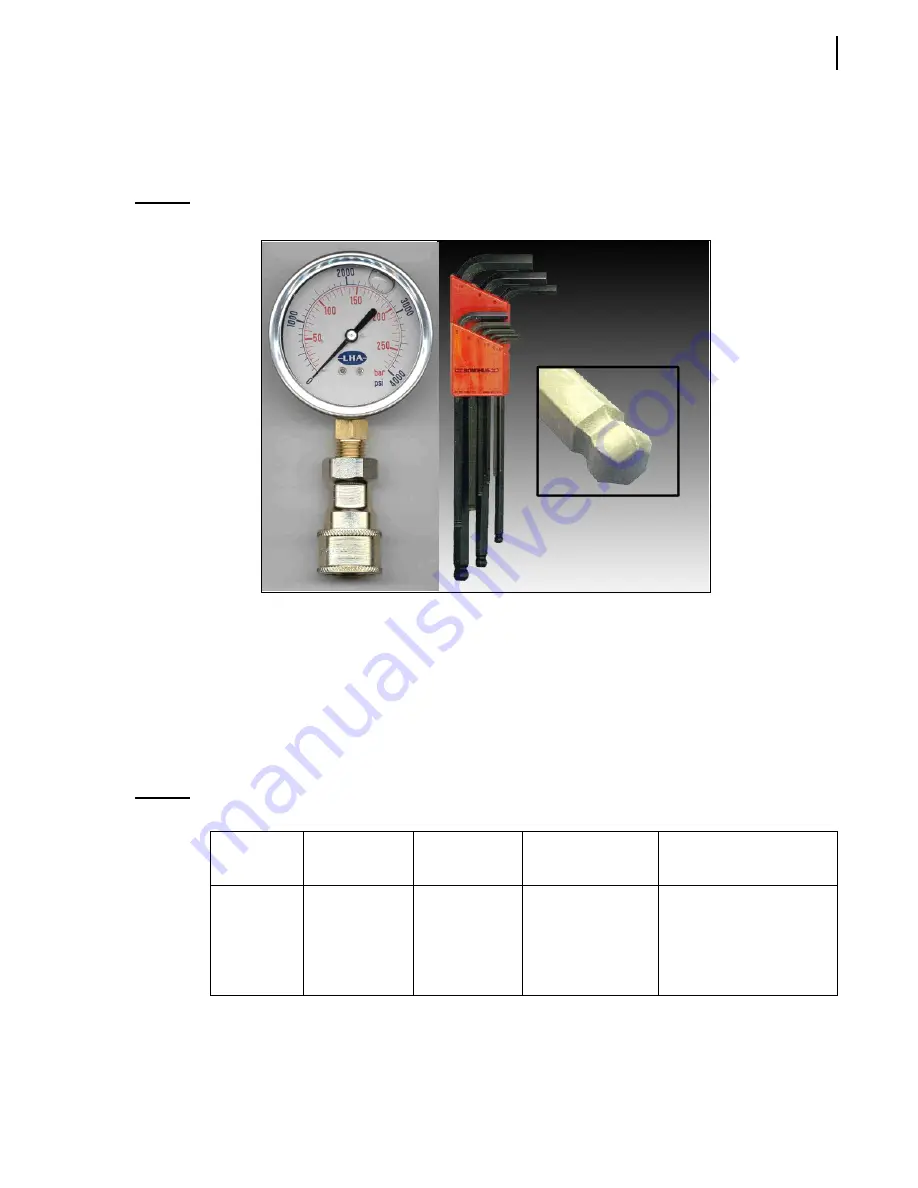
A 0–4000
psi pressure gauge as well as a set of ball-end hex keys are required to adjust pressure and
relief valves (see Figure 5-10).
Figure 5-10 Pressure gauge and ball-end hex key
Adjusting Vane Pump Relief Valves (if equipped)
The body and arm sections of the dual vane pump may have a relief valve on their dump valve.
Adjustment of vane pump relief valves, either on the pump or on the chassis, must be done before
adjusting the relief valve of the directional control valve.
The following pressure chart gives the proper adjustment pressure for body functions. Use this chart
to adjust the relief valve for the body vane pump. For arm functions, see
Table 1
Pressure chart
Pump
Chassis
Cylinder bore
(packer)
Main relief
pressure (±
50
psi)
Dump valve pressure
(if equipped) (±
50
psi)
Vane pump
6 ×
4
(tandem axle)
4 ×
2
(single axle)
4 inches
4 inches
3000
psi at idle
2000
psi at idle
3300
psi at idle
2200
psi at idle
Содержание Automizer Versa Hand
Страница 1: ...AUTOMIZER VERSA HANDTM MAINTENANCE MANUAL...
Страница 2: ......
Страница 3: ...AUTOMIZER VERSA HAND MAINTENANCE MANUAL...
Страница 26: ...18 Safety...
Страница 89: ...Lubrication 81 Figure 4 11 Lubrication chart Automizer...
Страница 90: ...82 Lubrication Figure 4 12 Lubrication chart Versa Hand arm...
Страница 94: ...86 Lubrication Figure 4 18 Cylinder retaining ring Cylinder retaining ring...
Страница 95: ...Lubrication 87 Packer Lubrication Points...
Страница 96: ...88 Lubrication Hopper Door Hopper door latch Hopper door hinges...
Страница 105: ...Hydraulic System 97...
Страница 127: ...Hydraulic System 119 Figure 5 29 Detecting cylinder internal leaks 1 2 3 4 5 A A A...
Страница 128: ...120 Hydraulic System Main Hydraulic Schematic...
Страница 129: ...Hydraulic System 121 Hydraulic Schematic 96 Gallon Gripper...
Страница 130: ...122 Hydraulic System Hydraulic Schematic 300 Gallon Gripper...
Страница 131: ...Hydraulic System 123...
Страница 132: ...124 Hydraulic System...
Страница 137: ...Electrical System 129 Electrical Schematics Console 1...
Страница 138: ...130 Electrical System Console 2...
Страница 139: ...Electrical System 131 Arm Control...
Страница 140: ...132 Electrical System Chassis...
Страница 141: ...Electrical System 133 Main Body...
Страница 142: ...134 Electrical System Hopper...
Страница 143: ...Electrical System 135 Arm...
Страница 144: ...136 Electrical System...
Страница 151: ...Pneumatic System 143 Pneumatic System Schematic...
Страница 152: ...144 Pneumatic System...
Страница 155: ...Troubleshooting 147 Figure 8 4 Ball end hex wrench metric and SAE...
Страница 164: ...156 Troubleshooting Figure 8 9 Tailgate locking mechanism...
Страница 166: ...158 Troubleshooting...
Страница 174: ...166 Lifting Arm Figure 10 1 Mounting bolts Figure 10 2 Rollers and bearings Figure 10 3 Bolt locks Bearings Rollers...
Страница 189: ...Lifting Arm 181...


