Page 12
LAARS Heating Systems
2400-435 tee
(to separate
venting from
combustion air)
4" air terminal
(field-supplied)
4" combustion air pipe
Fan
Combustion
Chamber
combustion
air
2400-409 condensate trap
(used if vent height is
greater than 7 feet)
2400-416
concentric rain cap
(use only on systems
with condensate trap)
2400-370
vertical vent cap
(can be used on system with
or without condensate trap)
2400-426
3" vent termination
with screen
2400-435 tee
(to separate
venting from
combustion
air)
4" air terminal
(field-supplied)
4" combustion air pipe
(15 equivalent feet, maximum)
3" diameter vent
(50 equivalent feet, maximum)
Fan
Combustion
Chamber
vent
gases
combustion
air
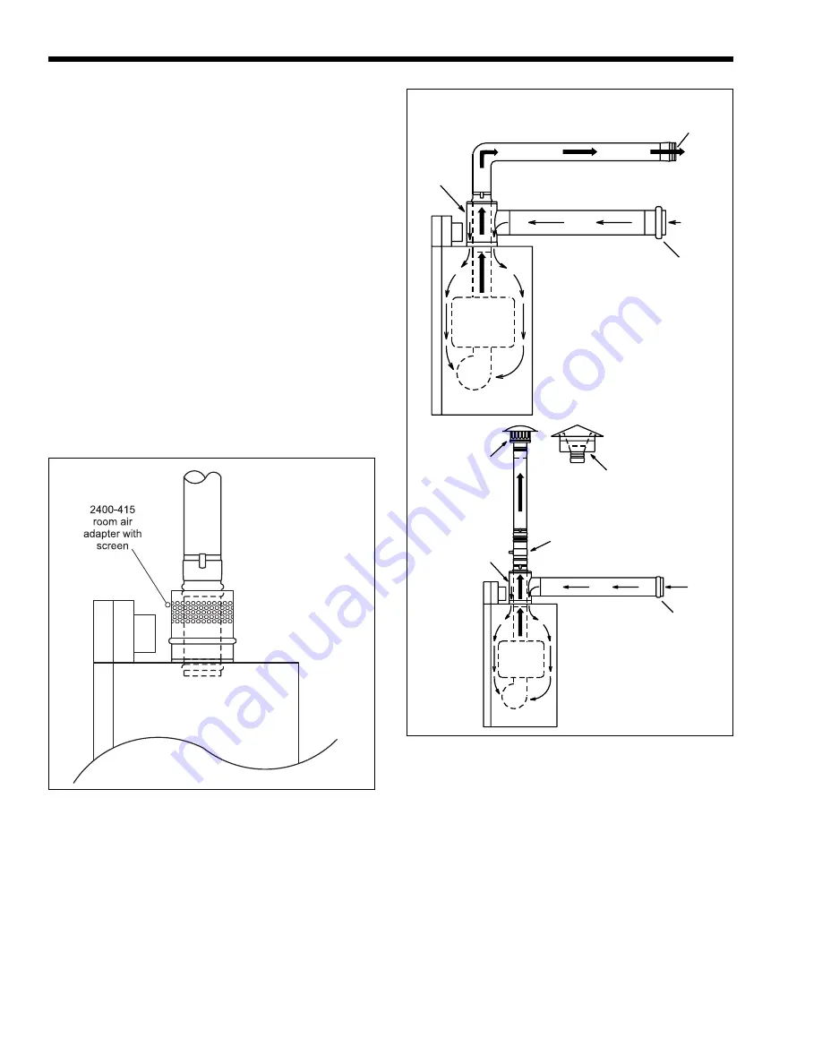
Figure 14. Combustion Air from Room.
The opening shall directly communicate with the
outdoors or shall communicate through a vertical
or horizontal duct to the outdoors or spaces that
freely communicate with the outdoors and shall
have a minimum free area of:
b1. 1 in.
2
/3000 Btu/hr (700 mm
2
/kW) of total
input rating of all equipment in the
enclosure,
and
b2. Not less than the sum of the areas of all
vent connectors in the confined space.
2.3.3 Connecting Special Gas Vent to
the Appliance
When drawing combustion air from the adjacent
space, part number 2400-415 (room adapter with
screen) can be used. One portion of this assembly
connects to the 5" air collar (with a screen for the
combustion air) and the other part connects to the 3"
flue opening (see Figure 14). The rest of the 3" vent
system can be connected to the adapter within the
2400-415.
2.4 Non-Concentric Combustion Air
An alternate, non-concentric combustion air
source may be installed (as shown in Figure 15),
provided that the minimum 4" diameter combustion
air duct does not exceed 15' (4.6m). Termination
should include an air screen and be located in a
qualified air space (see Section 2.3) or outside.
Separated combustion air / flue gas may be
considered either “mechanical draft” or “direct vent”.
To be considered “direct vent”, all of the combustion
air and flue gas piping must be sealed stainless steel
special gas vent, listed to U.L. 1738 and U.L.C. 636.
When the system meets this requirement, vent
terminal clearances may be less than that of a non-
direct vent system. See Figure 8 for direct vent
terminal clearances.
The combustion air pipe may be galvanized
material, but if used, the system is a “mechanical
vent” system, and the vent terminal clearances must be
per the rules for “mechanical vent” systems. See
Figure 8.
SECTION 3.
3.1 Gas Piping
The appliance requires an inlet gas pressure of at
least 4" w.c. (1.0kPa) and no greater than 13" WC
Non-Concentric Direct Vent with
Horizontal Vent.
Non-Concentric Direct Vent with
Vertical Vent.
Figure 15. Non-Concentric Combustion Air.


