La San Marco NEW 85 Скачать руководство пользователя страница 14

31

ENGLISH

If using flexible metal tubes for connection to the gas supply, interpose an appropriate G 1/2” female nipple 
(gas-tight thread) according to ISO 7-1 Standard and a G 1/2” male nipple (thread is not gas-tight) according 
to ISO 228-1 Standard; interpose a suitable gas-tight gasket.
When the connection is completed, open the gas flow upstream of the appliance and, using a soapy solution 
(never a free flame), check the perfect tightness of the connection.

7.2 Venting the combustion fumes

In relation to the venting of the combustion fumes, the appliance is of Type A1: i.e., it draws in the air required 
for combustion from the room and discharges the fumes in the same environment.
Place particular attention to the volume of the room where the appliance is to be installed: this should be at 
least 12 m

3

.

If the room has a smaller volume, it will be necessary to install the appliance directly under a suction hood, 
and also to provide a combustion air intake with a free-flow cross section of al least 100 cm

2

.

7.3 Ignition

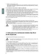
Press and turn the gas valve knob (51) counterclockwise to the position of the flame symbol, as shown in Fig. 
B. While holding the knob pressed, push a few times the burner ignition button, marked with the star symbol 
(53) to ignite the burner (piezoelectric ignition).
When the flame is lit, check through the relative hole (54), while keeping the gas knob pressed for 5-10 secon-
ds. After this period, if the flame does not remain lit, repeat the ignition operation again.

7.4 Changing the calibration

The appliance is prearranged to operate with the gas indicated in the relative settings tag attached to the 
appliance. The information regarding the air setting, injector, rated and reduced heat flow are shown in Tables 
1 and 2. The data that correspond with each model are indicated by the next-to-last character of the code for 
the relative model. For example, the model code shown on the tag for the gas part characteristic 85-E-3-G 
shows number 3 in the next-to-last digit.
In this case, refer to the data shown in Tables 1 and 2, respectively, in the column headed “3 Units”.
If you wish to change the calibration of the appliance, proceed as follows:
Unscrew the primary air adjusting ring nut (55 - Fig. C) to expose the nozzle (56). Using the relative wrench, 
unscrew the nozzle (56) and replace it with the proper one indicated in Table 2, checking that the diameter 
marked on the same nozzle corresponds to the right diameter.

1° GRUPPO

1

53

51

54

2

1

0

2° GRUPPO

Table 1 - Adjusting the primary air (Fig. C)


Gas 

2 Units  

3 Units  

4 Units


GPL 

L = 8 mm  L = 10 mm  L = 12 mm 

  (G30/G31) 

  Nat. gas  

L = 4 mm 

L = 4 mm 

L = 4 mm 


(G20)


Qn = Rated heat flow  


Qnr = Reduced rated heat flow    

Table 2 - Nozzle diameters in 100/mm


Gas 

2 Units  

3 Units  

4 Units


GPL 

40 

55 

65   

  (G30/G31) 

  Nat. gas  

60X 

81X 

90X 


(G20)

  Qn (kW) 

0,75 

1,45 

1,9

  Qnr (kW) 

N.A. 

1,0 

1,3

Содержание NEW 85

Страница 1: ...S 85 S E DE BEDIENUNG UND WARTUNGSANLEITUNG SERIE 85 S E ES MODO DE EMPLEOY MANTENIMIENTO SERIE 85 S E PT UTILIZA O E MANUTEN O S RIE 85 S E EL XPH H KAI YNTHP H EIPA 85 E MACCHINE CAFF ESPRESSO ESPRE...

Страница 2: ...19 ENGLISH OPERATION AND MAINTENANCE SERIES 85 S E...

Страница 3: ...2 Calibration of pump pressure pag 28 6 3 Calibration of water pressure in the boiler pag 28 6 4 Heating the water in the boiler pag 28 6 5 Electric cup warmer Optional pag 29 6 6 Steam delivery pag...

Страница 4: ...GJYFE BOE PS NPCJMF HVBSET SFNPWFE PS XJUI UIF TBGFUZ EFWJDFT DVU PGG 5IF TBGFUZ EFWJDFT NVTU BCTPMVUFMZ OFWFS CF SFNP WFE PS UBNQFSFE XJUI 5IF QBOFMT DPWFSJOH UIF NBDIJOF NVTU OPU CF SFNPWFE BT UIF...

Страница 5: ...22 ENGLISH 12 13 14 15 16 17 18 1 2 3 4 5 6 7 8 9 10 11 2 Exploded diagrams 19 20 Mod 85 S Mod 85 E...

Страница 6: ...ever 15 Hot water spout 16 Gas burner ignition button 17 Gas burner safety button 18 Two scale pressure gauge 19 Coffee serving button 20 Visual level indicator 21 Boiler water drain tap 22 Automatic...

Страница 7: ...automatic portions can be programmed on each brewing unit r PU XBUFS BOE TUFBN delivery on all models r VUPNBUJD XBUFS MFWFM boiler is automatically refilled on all models NO OF BREWING UNITS BOILER C...

Страница 8: ...er softener rubber drain hose with steel coil for water drain 3 8 nipples for hose connection to water supply tube cleaning brush for serving units pump suction filter on request braided 600 mm stainl...

Страница 9: ...UIF NBDIJOF UP UIF QPXFS TVQQMZ NBLF TVSF UIBU UIF EBUB PO UIF SBUJOH UBH DPSSFTQPOE UP UIF BWBJMBCMF QPXFS TVQQMZ 5IF UBH JT MPDBUFE PO UIF MFGU TJEF PG UIF NBDIJOF BOE DBO CF BDDFTTFE CZ SFNPWJOH UI...

Страница 10: ...ACK BROWN YEL GREEN BLUE BLACK BROWN BLACK YEL GREEN BLUE BLACK BROWN BLACK YEL GREEN BLACK BLACK BROWN BLUE YEL GREEN BLUE BROWN YEL GREEN N L N L3 L2 L1 N L3 L2 L1 L3 L2 L1 L3 L2 L1 N L N L 1 HEATIN...

Страница 11: ...sired value by oper ating on the pump screw the pressure is increased by turning clockwise it is decreased by turning counter clockwise As shown in the following figure there are three different cases...

Страница 12: ...d during a coffee brewing cycle Button 10 can also be used to brew the desired quantity of coffee manually press this button to start brewing and presse the button a second time to stop brewing when t...

Страница 13: ...cient water from the main water system etc After 1 30 the pump motor will shut down Note If the machine shuts down as described above call your local service technician t P OPU VTF XBUFS TQSBZT TUFBN...

Страница 14: ...e is lit check through the relative hole 54 while keeping the gas knob pressed for 5 10 secon ds After this period if the flame does not remain lit repeat the ignition operation again 7 4 Changing the...

Страница 15: ...perates on the valve 51 whose probe 52 must be licked by the flame from the burner 50 If the probe is not enveloped by the flame the gas flow will be automa tically shut off 2 Thermostat 59 The thermo...

Страница 16: ...a overvoltage overcurrent or insufficient or irregular power supply 10 Declaration of conformity The manufacturer La San Marco S p A 34072 Gradisca d Isonzo GO Italy Via Padre e Figlio Venuti 10 phone...

Страница 17: ...DPOUSPM VOJU JT defective r IFDL UIF BVUPMFWFM DJSDVJU UIF NBO ual charging button and the boiler heat exchangers r 3FQMBDF XPSO PS EBNBHFE QBSUT UP eliminate the leak r Check the wiring that feeds th...

Страница 18: ...filter on unit clogged e Filter holes widened filter cup r 4QSJOLMFS GJMUFS PO VOJU clogged r PGGFF FYUSBDUJPO UBLFT B MPOH time due to clogged filter r PGGFF FYUSBDUJPO UPP GBTU EVF to clogged sprin...

Страница 19: ...La San Marco S p A M X GX i c f M elk iX jZX jfeqf fi q X kXcp K c 0 0 Xo 0 0 _kkg1 nnn cXjXedXiZf Zfd dX c1 e f7cXjXedXiZf Zfd...

Отзывы: