La San Marco NEW 85 Скачать руководство пользователя страница 11

28

ENGLISH

6. Operating instructions

6.1 Filling the boiler 


Checking the position of the taps in the water system

a)  Remove the coffee ground collection tray with grille. Now, check for the following configuration:

r#PJMFSESBJOUBQDMPTFE

r5BQPOUIFBVUPNBUJDMFWFMDPOUSPMWBMWFPQFO

r5BQPOUIFBVUPNBUJDMFWFMDPOUSPMWBMWFPQFO

b)  Install the coffee ground collection tray with grille
c)  Open the main water fill tap 33 
d)  Open a steam delivery lever 5 to allow air to escape from the system as the boiler is filled.

Mod. 85 - Practical - S/E 

e)  Move  the  main  switch  1  to  position  1  to  fill  the  boiler  automatically  without  activating  the  heating  ele-

ments. When the water reaches the probe, the “MAX” led will light up. When the boiler is full, turn the 
main switch to working position 2.

Mod. 85 - S/E - 2 - 3 - 4

f)  Make sure that the main switch 1 is in position “zero”.
g)  Press and hold down the button 14 until the sight glass 20 is 3/4 full.

6.2 Calibration of pump pressure

a)  Once the boiler is filled, turn the main switch to position 2 (the heating elements start to heat the water).
b)  Press the continuous-feeding push button 19 for the manual serving machines or the push button 10 for 

the electronic machines with automatic serving, so that the water flows out of the unit corresponding to 
the pressed button.

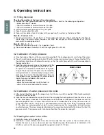
c)  Read the water pressure value on the lower part of the 

pressure gauge 18. The optimum pressure is 9 bar.


The pressure is adjusted to the desired value by oper-
ating on the pump screw: the pressure is increased by 
turning clockwise; it is decreased by turning counter-
clockwise. As shown in the following figure, there are 
three different cases for adjusting this screw, depend-
ing on the pump installed on the machine:


- adjust only the screw


- adjust the screw and lock it with the lock nut


- unscrew the cap nut and adjust the screw.

6.3 Calibration of water pressure in the boiler

a)  After having filled the boiler to the proper level, turn the main switch to position 2 (the heating elements 

will start to heat the water).

b)  Open the lever-controlled steam valve 5 to vent the air during the heating phase. Close the valve as soon 

as the steam phase is reached. The steam pressure in the boiler can be read on the upper scale of the 
pressure gauge 18 from 0 to 3 bar. The pressure rises to the calibration value of the pressure switch 27 
in the range from 0.9 to 1.1 bar. To vary the steam pressure, turn the screw 28 on the pressure switch 
27. The pressure is decreased by turning the screw clockwise and it is increased by turning the screw 
counterclockwise. The screw is adjusted by means of a screwdriver inserted into the hole on the lid of the 
pressure switch. The pressure switch can be reached from the upper tray and grill.

6.4 Heating the water in the boiler

a)  Rotate the main switch to position 2.
b)  Hold  down  a  steam  delivery  lever  5  to  allow  air  to  escape  from  the  system  as  the  machine  heats  up. 

Release the lever as soon as steam escapes from the delivery pipe. Boiler pressure is indicated on the 
0-to-3-bar scale on the pressure gauge 18 (suggested value: 0.9-1.2 bar).

PUMP SCREW

Содержание NEW 85

Страница 1: ...S 85 S E DE BEDIENUNG UND WARTUNGSANLEITUNG SERIE 85 S E ES MODO DE EMPLEOY MANTENIMIENTO SERIE 85 S E PT UTILIZA O E MANUTEN O S RIE 85 S E EL XPH H KAI YNTHP H EIPA 85 E MACCHINE CAFF ESPRESSO ESPRE...

Страница 2: ...19 ENGLISH OPERATION AND MAINTENANCE SERIES 85 S E...

Страница 3: ...2 Calibration of pump pressure pag 28 6 3 Calibration of water pressure in the boiler pag 28 6 4 Heating the water in the boiler pag 28 6 5 Electric cup warmer Optional pag 29 6 6 Steam delivery pag...

Страница 4: ...GJYFE BOE PS NPCJMF HVBSET SFNPWFE PS XJUI UIF TBGFUZ EFWJDFT DVU PGG 5IF TBGFUZ EFWJDFT NVTU BCTPMVUFMZ OFWFS CF SFNP WFE PS UBNQFSFE XJUI 5IF QBOFMT DPWFSJOH UIF NBDIJOF NVTU OPU CF SFNPWFE BT UIF...

Страница 5: ...22 ENGLISH 12 13 14 15 16 17 18 1 2 3 4 5 6 7 8 9 10 11 2 Exploded diagrams 19 20 Mod 85 S Mod 85 E...

Страница 6: ...ever 15 Hot water spout 16 Gas burner ignition button 17 Gas burner safety button 18 Two scale pressure gauge 19 Coffee serving button 20 Visual level indicator 21 Boiler water drain tap 22 Automatic...

Страница 7: ...automatic portions can be programmed on each brewing unit r PU XBUFS BOE TUFBN delivery on all models r VUPNBUJD XBUFS MFWFM boiler is automatically refilled on all models NO OF BREWING UNITS BOILER C...

Страница 8: ...er softener rubber drain hose with steel coil for water drain 3 8 nipples for hose connection to water supply tube cleaning brush for serving units pump suction filter on request braided 600 mm stainl...

Страница 9: ...UIF NBDIJOF UP UIF QPXFS TVQQMZ NBLF TVSF UIBU UIF EBUB PO UIF SBUJOH UBH DPSSFTQPOE UP UIF BWBJMBCMF QPXFS TVQQMZ 5IF UBH JT MPDBUFE PO UIF MFGU TJEF PG UIF NBDIJOF BOE DBO CF BDDFTTFE CZ SFNPWJOH UI...

Страница 10: ...ACK BROWN YEL GREEN BLUE BLACK BROWN BLACK YEL GREEN BLUE BLACK BROWN BLACK YEL GREEN BLACK BLACK BROWN BLUE YEL GREEN BLUE BROWN YEL GREEN N L N L3 L2 L1 N L3 L2 L1 L3 L2 L1 L3 L2 L1 N L N L 1 HEATIN...

Страница 11: ...sired value by oper ating on the pump screw the pressure is increased by turning clockwise it is decreased by turning counter clockwise As shown in the following figure there are three different cases...

Страница 12: ...d during a coffee brewing cycle Button 10 can also be used to brew the desired quantity of coffee manually press this button to start brewing and presse the button a second time to stop brewing when t...

Страница 13: ...cient water from the main water system etc After 1 30 the pump motor will shut down Note If the machine shuts down as described above call your local service technician t P OPU VTF XBUFS TQSBZT TUFBN...

Страница 14: ...e is lit check through the relative hole 54 while keeping the gas knob pressed for 5 10 secon ds After this period if the flame does not remain lit repeat the ignition operation again 7 4 Changing the...

Страница 15: ...perates on the valve 51 whose probe 52 must be licked by the flame from the burner 50 If the probe is not enveloped by the flame the gas flow will be automa tically shut off 2 Thermostat 59 The thermo...

Страница 16: ...a overvoltage overcurrent or insufficient or irregular power supply 10 Declaration of conformity The manufacturer La San Marco S p A 34072 Gradisca d Isonzo GO Italy Via Padre e Figlio Venuti 10 phone...

Страница 17: ...DPOUSPM VOJU JT defective r IFDL UIF BVUPMFWFM DJSDVJU UIF NBO ual charging button and the boiler heat exchangers r 3FQMBDF XPSO PS EBNBHFE QBSUT UP eliminate the leak r Check the wiring that feeds th...

Страница 18: ...filter on unit clogged e Filter holes widened filter cup r 4QSJOLMFS GJMUFS PO VOJU clogged r PGGFF FYUSBDUJPO UBLFT B MPOH time due to clogged filter r PGGFF FYUSBDUJPO UPP GBTU EVF to clogged sprin...

Страница 19: ...La San Marco S p A M X GX i c f M elk iX jZX jfeqf fi q X kXcp K c 0 0 Xo 0 0 _kkg1 nnn cXjXedXiZf Zfd dX c1 e f7cXjXedXiZf Zfd...

Отзывы: