Multi-Image Splicing Processor
11
Note:
since four transmitting cards are in a horizontal layout, horizontal mosaic
is needed then.
Step 2:
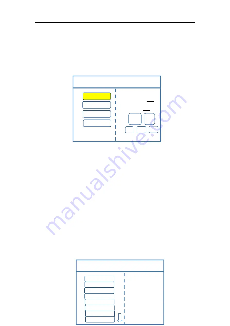
Click “OK” to return to main menu interface; select “Large screen
parameters” to set size of each output.
Note:
Input according to corresponding transmitting card size of each output
interface. For OUT1, its horizontal size is 1920 and vertical size 576; for OUT2, they
are 1920 and 576 respectively; for OUT3, they are 1920 and 576; for OUT4, 1120 and
576.
Step 3:
After inputting, click “Confirm” and return to main menu interface. The
large screen splicing is finished, select signal source needed to display on screen and
click corresponding key. For instance, for display of computer signal on large screen
and connection of computer DVI interface with “S1-DVI” port of the back device,
just click “S1” in the front which means choosing the signal to display on the screen.
Step 4:
After selecting signal and normal display of large screen, save all setting
data. Click “MENU” to enter into main menu interface, and then get into “Save
setting” interface to select “Mode 1” and click “OK”. Things will be fine when it
suggests saving successfully.
Screen Parameters
OUT1
OUT2
OUT3
OUT4
Select by Finger key
Vertical Size:1080
Confirm
Cancel
×
1
×
10
×
100
Horizontal size:1920
Rotate knob to select output
Click
“
OK
”
to adjust
Save Setting
Save Mode 1
Device Mode
Image Layout
Current mode does not exist!
Mode 1
Mode 2
Mode 3
Mode 4
Mode 5
Mode 6
Mode 7
Mode 8


