10
NOTE:
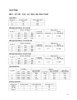
All the BTU requirements shown in the case data are for use on parallel systems
only. A minimum of 8% excess capacity should be added to all conventional single compressor
condensing units.
NOTE:
The air current is very important to the performance of these cases. The load
limit line (see load case selection) is the indicator of the inside edge of the air current and at no
time should product, signs, debris, etc. interfere with air current.
NOTE:
All electrical
data based on 115V and unlighted shelves. For lighted shelves, add 0.25
amps per shelf.
NOTE:
For sizing conventional/ individual condensing units, add 8% to BTU Load.
NOTE
: Temperature is measured in discharge air. Defrost frequency is at design conditions. Higher
temperature or humidity may require more defrost and longer fail-safes. These cases are not designed to
operate environments where the ambient temperature is greater than 75ºF and the relative humidity is
greater than 55%. Off-cycle defrost is the recommended defrost for all Q case models. Electric defrost
and hot gas defrost are available for installations requiring a positive defrost.
CAUTION
: Failure to maintain maximum design conditions may result in operational issues such
as: increased BTU load, high product temperature, coil icing, product frosting, and external sweating.
CAUTION
: Failure to properly install electrical wiring and control wiring as per wiring
diagram(s), defrost settings, and temperature set-points may result in operational issues such as:
increased BTU load, high product temperature, coil icing, product frosting, and external sweating.
Case Installation
These display cases may be installed individually or in a continuous lineup consisting of several 4’, 8’
and 12’ sections using a joint kit.
Preparation
Prepare the installation area as follows:
1.
Clean area where case is to be installed.
2.
Verify installation area is at least 15 feet from any outside entrances or heating and cooling
outlets.
3.
Verify at least 2 feet of distance between hot and cold cases.
CAUTION
:
To prevent condensation on the end panels of cases, a minimum of 6.0 inches
between walls or other cases is required for airflow. If 6.0 inches is not possible, then the space between
Содержание QILG 06
Страница 2: ...2 ...
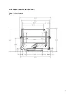
Страница 7: ...7 Plan View and Cross Sections QILG Cross Section ...
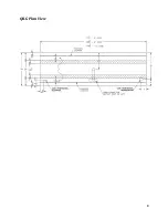
Страница 8: ...8 QILG Plan View ...
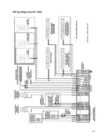
Страница 23: ...23 Wiring Diagram Per Side ...
Страница 34: ...34 ...
Страница 35: ...35 ...

