Chapter 6 - SAT Measuring Range
33
106 V3.2
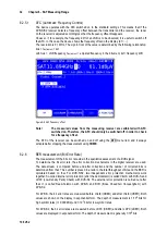
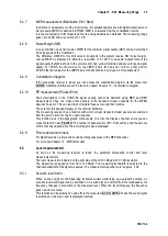
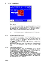
MER measurement (Modulation Error Rate)
6.2.7
In addition to measurement of the bit error rate, it is established practice with digital transmission to
also measure MER. It is defined in ETR290. MER is calculated from the constellation points.
It is the counterpart to S/N measurement with analog transmission methods. The measuring range
goes up to 20 dB with a resolution of 0.1 dB.
Noise Margin (NM)
6.2.8
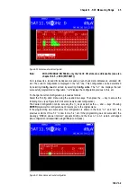
In case of white noise a limit value of MER for the minimum signal quality (QEF) can be determined
which depends on the modulation.
The difference of MER to this limit value corresponds to the system reserve NM (noise margin).
Just as MER it is displayed in dB with a resolution of 0.1 dB. For an easier assessment of the
signal quality the NM is shown in the colors red for bad, yellow for limited and green for good signal
quality. For DVB-S the limit values for the VBER (>2e-4 for bad and <1e-6 for good) and for
DVB-S2 the limit values for the LBER(>2e-4 for bad) will also be included in this assessment
Constellation diagram
6.2.9
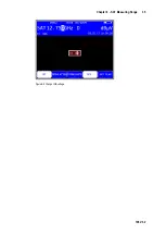
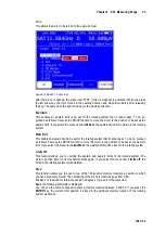
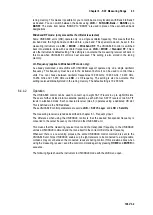
If the measuring receiver is tuned, you can access the constellation diagram via the menu item
CONST
. Additional information can be found in chapter Chapter 13 - Constellation diagram.
PE measurement (Packet Error)
6.2.10
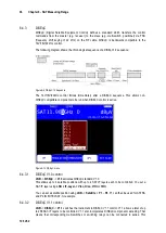
Short interruptions in the DVB-S/S2 signal usually cannot be detected using MER and BER
measurement. They can make entire packets in the transport stream unusable for the MPEG
decoder, however. This can lead to short picture freezes or sound that crackles.
The extent of this depends largely on the receiver hardware.
The measuring receiver has a function with which corrupt transport stream packets are summed
from the point in time of entry of a new frequency.
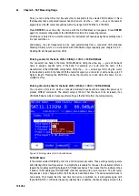
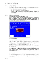
This function runs in the background continuously. To active the display of packet errors you can
press the function key
PE-INFO
. The number of packet errors (PE = Packet Error) and the amount
of time that has passed since the last tuning process is displayed.
Picture and sound check
6.2.11
For digital television, picture and sound decoding take place in the MPEG decoder.
For more see Chapter 12 - MPEG Decoder.
6.3
Level measurement
As soon as the measuring receiver is tuned, the automatic attenuation control and level
measurement starts.
The level measured is indicated on the right side of the LCD in dBµV with 0.1 dB resolution.
The measuring range spans from 30 to 120 dBµV. The measuring bandwidth is adjusted to the
channel bandwidth of the signal measured. The measurement repetition rate is approx. 3 Hz.
Acoustic level trend
6.3.1
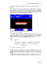
When no line of sight to the measuring instrument exists while lining up a parabolic antenna, an
acoustic level trend signal can be switched on. A sound signal is emitted from the loudspeaker. It's
frequency changes in proportion to the measured level. When the level increases, the frequency
goes up and vice versa.
This function can be switched on and off via the menu item
ACOU. LEVEL
. When the sound signal
is switched on, the menu item is displayed inverted.


