


4 | kvm-tec
kvm-tec | 5
4.3 ManagIng user details rights and Groups
4.6 Installing dual-head or multi-head system
4.7 Enable user groups and rights and login access
4.8 Auto-connect to a free computer after an interruption
4.9 Installing a private connection
4.10 Enable the user-pc binding mode
4.11 Enable the disconnect on PC Power Down option
4.12 Hidding system status menu
5. Troubleshooting & First Aid
6.1 Requirements for CAT5e/6/7 cables
8. Maintance & Care , Disposal
9. Warranty & extended warranty
TABLE of CoNTENTS
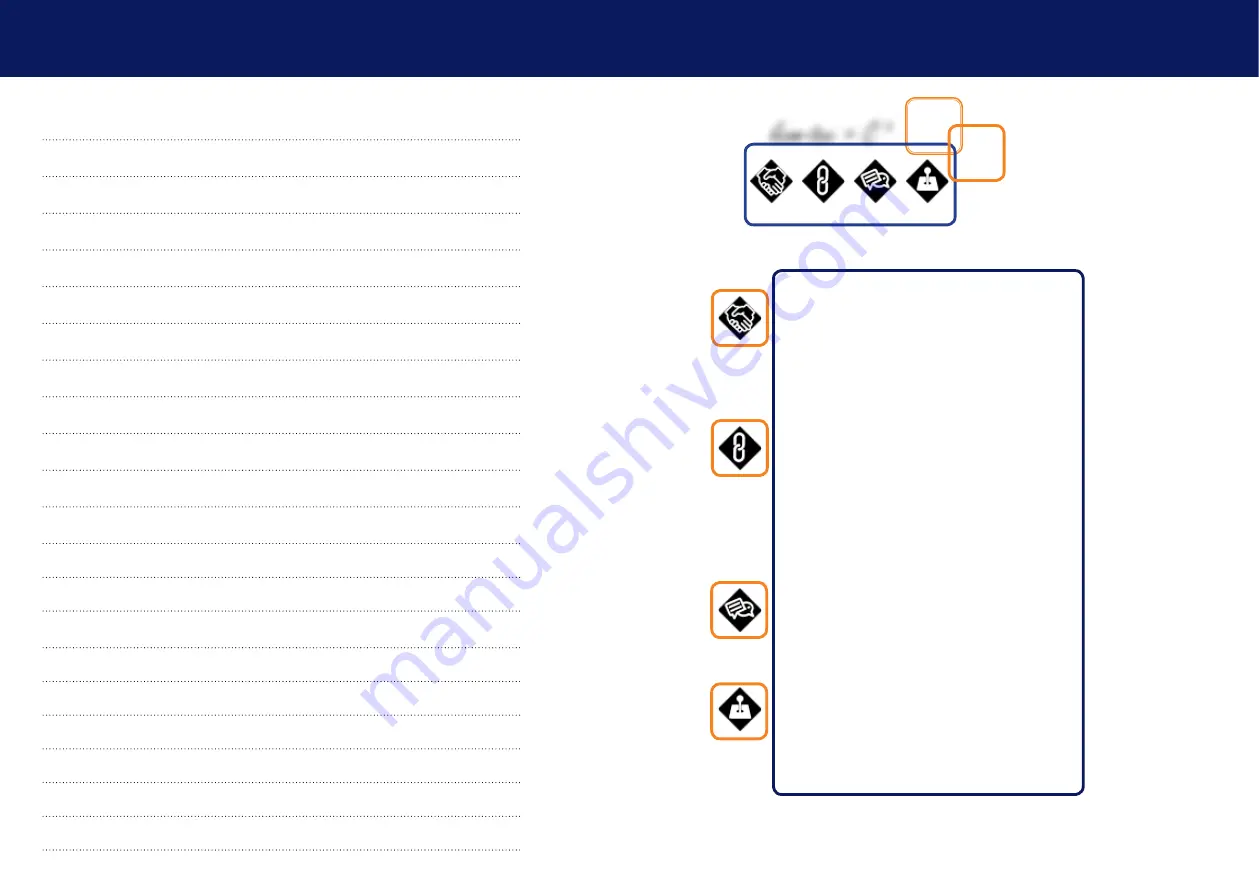
CONNECT
kvm-tec Extender in Matrix Switching Systems and
you can go up to 2000 endpoints and have a super fast switching.
You can connect a wide range of different sources (servers,
operator workstation,PC, surveillance camers, video walls and
much more) and operate & control the system with centralized
management
Network Environemt; 1 or 10 Gbit bandwith
IGMP Snooping ( for videosharing)
COLLABORATE
kvm-tec extenders are installed with Standard
Networkcomponetnst in a separate network, therefore cyber
attacks are impossible. The huge benefit is safety against cyber
attacks and reliability in various applications , such as medicine,
airports, air traffic control, industry, public buildings. The KVM
Technology over IP benfits from the high security level in PC
networks.
Another feature is the kvm-tec feature „USB save“. This feature
prevents the intrusion of viruses via the USB interface by deacti-
vating mass storage devices.
Mix & Match for all kvm-tec extenders, because all units can work
in real time with 60Hz in Full HD or 4K resolution.
COMMUNICATE
in your Switching System with our kvm-tec
Switching Manager Software. The local and remote Extender are
arranged in an optimized way and the Extender status is high
-
lighted in color. With the kvm-tec Systems computers and servers
can be located away from work desk into central server room for
a high security level. The environment heat and noise are re-
duced at the work station and an ergonomic and quiet workplace
for all users is possible
CONTROL
your application in a much better way with all our
in-house developments, like USB 2.0 transmission, video com-
pression without latency, only one cable for USB and video
transmission ,zero latency. With our unique features each user
can access multiple PC sources and can control and operate up
to 16 screens with one mouse & keyboard. Video sharing can
be done seamless and a central video wall can be integrated for
sharing all informations in real time
connect collaborate communicate control
kvm-tec = C
4
Содержание Smartline SVX1
Страница 36: ...70 kvm tec 11 Notes...