KVM-TEC Smartline SVX1 Скачать руководство пользователя страница 10

18    |    kvm-tec

3. extender menu/settings

2. installation of the extender


2.4 sTART Up

To start up the system without switch:

1.  Make sure that the two monitors and the computer are switched on.
2.  If you are using a Network Switch, connect the power supply to an earthed wall socket. 
3.  Connect both extender 

power supplies

 (C) to an earthed wall socket. Both extenders will  


start an initialisation process. The red status LED blinks a few seconds. After a few seconds  


the status LED lights green. The monitor will displays your computer’s desktop or any open  


applications.

2.5 REMOVINg A CATx CABLE

To remove a CATx cable:

•  Press the latch down and slowly pull the cable out.

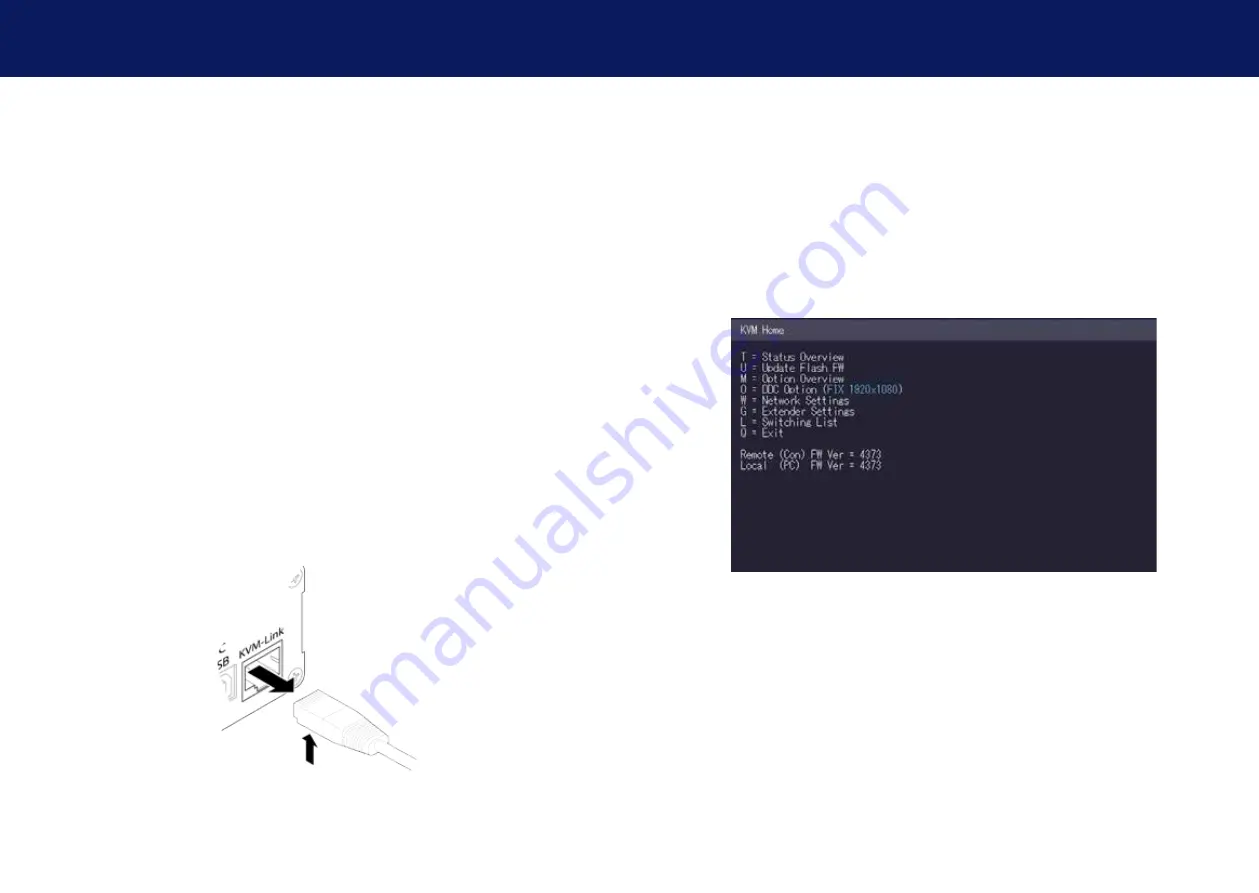
3.1 hOW TO ACCEss ThE MAIN MENU

Use the monitor and keyboard to get access to the main menu. 

To access the main menu:
1.  Make sure the extenders, the monitors and the computer are switched on.

2.  Press the Scroll Lock key on your keyboard quickly five times. The main menu appears  


with an overview of the sub-menus. 

3.  To access a sub-menu press the applicable key.

kvm-tec    |    19

3. EXTENDER MENU/SETTINGS

Содержание Smartline SVX1

Страница 1: ...Check out our Installation Channel www kvm tec com line smart kvm tec User Manual Smartline SVX 6501 SET 6501L CPU LOCAL 6501R CON REMOTE connect collaborate communicate control kvm tec C 4...

Страница 2: ...date 24 3 4 3 Performing a network update 25 3 5 Unlock an upgrade 26 3 6 Enable or disable USB Memory upgrade 27 3 7 Defining what DDC data your pc uses 28 3 8 Changing the network settings 28 3 9 Ch...

Страница 3: ...ible The huge benefit is safety against cyber attacks and reliability in various applications such as medicine airports air traffic control industry public buildings The KVM Technology over IP benfits...

Страница 4: ...ns Keep all safety information and instructions for future reference and pass them on to subsequent users of the product The manufacturer is not liable for cases of material damage or personal injury...

Страница 5: ...g all connections before cleaning the product Do not use wipes or chemicals as these could damage the surface Wipe the housing with a damp cloth Electrical electronic parts must not be cleaned Alterat...

Страница 6: ...for CAT5 6 7 cable 6 Power Status LED Displays the status of the extender Remote CON Extender Nr Name Function 7 Monitor Out Connection to Monitor 8 DC Connection for 12 V power supply 9 USB USB conn...

Страница 7: ...ast Yes Red Green V fast Yes Yellow No Yellow Slow Yes Green Yes Green V fast Yes Main LED RJ45 Socket LEDs 2 1 Unpacking and checking the contents Before using the product for the first time it shoul...

Страница 8: ...asterline MVX extenders It consists of 19 Rack Shelf alu faceplate and power supply Rack Mounting Kit RMK FRN Part No 6132 The rack mounting kit RMK FRN is used to mount kvm tec Smartline SVX and Mast...

Страница 9: ...remote CON Connect the CON Remote and the CPU Local Unit to the included 12V 1A power sup ply Connect the USB cable to a USB port on your PC and connect the other end of the USB cable to the CPU Local...

Страница 10: ...seconds After a few seconds the status LED lights green The monitor will displays your computer s desktop or any open applications 2 5 Removing a CATx cable To remove a CATx cable Press the latch down...

Страница 11: ...enu the current status of the extender connection is displayed It provides information on the connection itself as well as resolution of the video channel and USB status The enabled options and the cu...

Страница 12: ...2 automatic update 3 networkupdate To perform a firmware update 1 Make sure the main menu is open 2 Press the U key The Update menu appears Press the N key to do a network update Press the A key to do...

Страница 13: ...e flashing of the light emitting diodes indicates when the update process is finished the light emitting diodes are then green 3 4 3 Performing a network update In the network update the devices that...

Страница 14: ...nfirm the upgrade has been unlocked return to the Options Overview menu and check that the relevant upgrade is now displayed in green 3 6 Enable or disable USB Memory upgrade The USB Memory upgrade al...

Страница 15: ...current DDC information The system is not applies the same settings after restarting the Extender 5 Press the buttons 4 to 8 to use a predefined resolution the is stored in the memory 6 Press ESC to...

Страница 16: ...utton to display the Local Setting menu Press the R button to display the Remote Settings menu 3 9 1 Changing the USB compatibility mode To enable disable the USB compatibility mode 1 From the Extende...

Страница 17: ...function 3 Press ESC to go back to the main menu 3 9 3 Turning on or off monitor synchronization The monitor synchronization can be turned on and off When enabled the refresh rate of the graphics car...

Страница 18: ...emote Settings menu appears 2 Press the L key The Menu Lock Menu appears 3 9 5 Using the power saving mode The power saving mode lets the extender turn off its video out when the remote extender does...

Страница 19: ...rty English Qwerty and German Qwertz To select a keyboard layout 1 From the Extender Settings menu press the R key The Remote Settings menu appears 2 Press the K key The Keyboard Locale menu opens Pre...

Страница 20: ...on Remote unit The status is listed as in use Green indicates a computer in the switching network that isn t connected to any work station Remote unit The status is listed as free Red indicates a comp...

Страница 21: ...r push to screen Such a command is only valid if the console which initiates the mirroring is currently connected to a local unit and has video and the other remote unit is free marked green To see th...

Страница 22: ...efine how you want the network system to operate Each of the modes available may individually be activated or deactivated by pressing the appropriate key You may have more than one selected depending...

Страница 23: ...the selected device connection Press the E key or Enter key to select a PC or workstation to create or break a connection to that unit Press the Q key to exit 4 3 ManagIng user details rights and Grou...

Страница 24: ...e entered with max 20 characters This name is displayed when informing other users who interrupted their connection Password Each user requires a password for the login Max 16 characters Rights There...

Страница 25: ...ser must have a PC bound to them That user will only be able to connect to that PC When selected the User Detail menu press RETURN a list of PCs on the network will be displayed to select from 4 4 Man...

Страница 26: ...Extender Detail menu opens 4 Use the Up and Down Arrow keys to select the name or group of the PC unit 5 Press the E key to edit the selected parameter Example There are the following 3 PC s Departmen...

Страница 27: ...ON extenders 1 Make sure that the Master View menu is open see chapter Network Networking Settings Master View and Network Mode 2 Press M The Multi Head configuration menu opens 3 Press the A key The...

Страница 28: ...option 1 Make sure the Network Mode menu is open see chapter How to access the Network Settings menu Master View and Network Mode 2 Press the P key to disable or enable the option 4 8 Auto connect to...

Страница 29: ...Mode menu is open see chapter Switches Menu Master View and Network Mode 2 Press V to enable or disable the option 3 To establish a private connection hold down the Shift key while selecting a new con...

Страница 30: ...unit to find a different local extender to connect to To enable the PC Power Down option 1 Make sure the Network Mode menu is open see chapter How to access the switching menu Master View and Network...

Страница 31: ...password system is activated you can define under what circumstances the user will be required to re enter their login details when switching I Immediately User and password must be re entered for ea...

Страница 32: ...lighting differently Different firmware To enter on screen menu check firmware version To enter the On screen menu press the Scroll Lock key five times in quick succession The currently installed firm...

Страница 33: ...1 2002 or EN 50173 1 2002 Schema EIA TIA 568 B Only use shielded installation cable with min cross section of 24 AWG throughout the length The shield should be contiguous and connected to both ends A...

Страница 34: ...e equipment The recycling of materials contributes to the conservation of natural resources Therefore do not dispose of your old electrical and electronic equipment with the unsorted municipal waste T...

Страница 35: ...Damage by lightning Always contact us first before sending back the product 10 Contact Address If you have any questions about our products please contact kvm tec or your dealer kvm tec electronic gmb...

Страница 36: ...70 kvm tec 11 Notes...

Отзывы: