Hitching the machine
14
14
Hitching the machine
NOTE
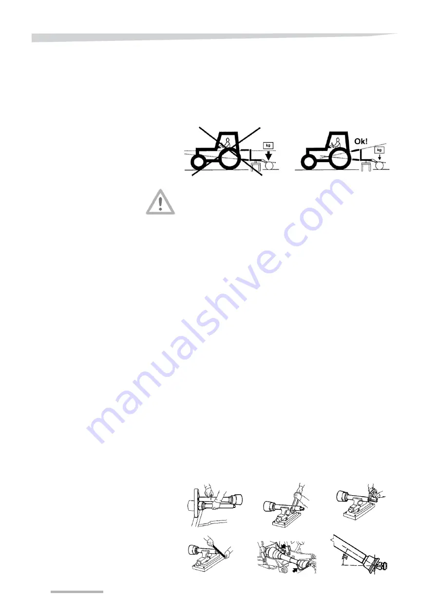
In working position, the top link of the tractor's hydraulic linkage
should slope down towards the tractor (see next figure).
This configuration enables the implement to overcome obstacles and
ensure that the roller is loaded correctly. Incorrect adjustment (e.g. top
and lower links parallel) will result in an excessive load on the
implement and the roller.
Tractor and implement combination: do not exceed the maximum
permitted weights!
The combination of the mounted implement and tractor must not
exceed the maximum permitted weight, i.e. the maximum permitted
axle loads and the load capacity of the tractor wheels. At least 20% of
the tractor weight must be supported on the front axle of the tractor.
Connection of the
drive shaft
Check the dimensions!
Before connecting the drive shaft, check that its dimensions are
suitable for attachment to the tractor's Pto.
If the drive shaft is too long, this could cause serious damage to the
transmissions of the tractor and the harrow, as well as to the shaft itself.
If the drive shaft is too short, the two halves of the shaft could become
separated with a consequent risk of serious injury and damage.
To check the length of the drive shaft, proceed as follows:
•
Place the two halves of the drive shaft assembly (the half
connected to the tractor Pto and the half connected to the
implement) side by side; the tractor Pto half and the implement half
should be parallel; the angle can be adjusted by way of the top link
of the hydraulic linkage.
•
If the sliding distance of the shafts is less than 40mm, then both the
halves will have to be shortened by a corresponding amount.
Maintain the difference in length between the outer tube and the
inner section.
•
Always make sure that the maximum coverage of the sliding element
is maintained. The coverage should be at least 1/3 during operation.
•
With the harrow in the working position, the angle of the drive shaft
should not exceed 20° (for example, at a working depth of 10 cm),
while the maximum permitted angle is 25°.
D
F
E
B
A
C


