-23-
a) Assembly
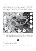
At first, remove the original left and right connecting brackets. Re-use the mounting
hardware to mount the connecting brackets (E) of the hydraulic rear attachment. Then
place the pin (I) in the rear hole of the 3-point yoke of the hitch frame. The hydraulic
cylinder (V) necessitates at least one single acting valve on the tractor. In order
to adapt additional implements of different categories (I or II) the hooks (A) as
well as the shims (B) can be assembled in different ways, either to the interior or
to the exterior of the rear frame (C), to obtain the desired width. The hooks (A)
can also be adjusted in height (two positions). The locks (D) are used to lock the
machine linkage in the hooks (A).
Note : When fitting hydraulic 3-point frame to EL 100N - 255, remove standard
adjusting rod fixation bracket bolted on the machine cross tube and bolt new
bracket (H) supplied with the hydraulic 3-point linkage on the 3-point frame
as shown in photo above.
b) Combination with a machine with PTO drive
(for example a pneumatic seed drill)
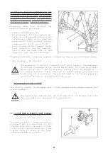
With the combination of the EL 100 N with a PTO powered machine, it is necessary to
fit the pivoting frame (P) in the upper position (see figure overleaf).
Содержание EL 100 N
Страница 1: ...ASSEMBLY OPERATOR S MANUAL EL 100 N POWER TILLER N 95458 A GB 12 1999...
Страница 10: ...8...
Страница 18: ...16...


