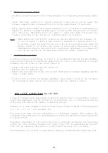
-12-
After mounting the power tiller, stabilize the tractor 3-point linkage with whatever
means are recommended i.e. the bars, chains etc. Couple the PTO shaft to the tractor
(with the gear lever in neutral position).
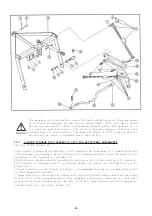
Adjust the top link (I) length to a position where the tiller input shaft (J) is
parallel to the ground.
In this position :
-
The 2 angles (K) between PTO yoke centre line and axes of the PTO sliding tubes
must be equal and not exceed 30°.
-
Overlap of sliding tubes (L) must be at least 22 cm (9").
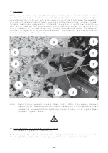
Disengage the tractor PTO shaft and lift the machine using the hydraulics.
In the raised position :
-
The 2 PTO sliding tubes must not completely overlap each other ; a safety gap (M)
of 1 cm (3/8") should exist between end of sliding tube and yoke.
-
Yoke angles (K) must not exceed 40°.
If above situation does not exist, proceed as follows :
-
Shorten both tubes by an equal length.
-
Decrease lifting height of the tractor lower link arms but ensure that there is
sufficient ground clearance under the rotor.
Repeat this adjustment each time the machine is mounted to a different tractor.
The working depth (2 to 20 cm - 3/4" to 7 7/8") should be controlled by either the
two wheels or with the two skids or with the roller which is available as optional
extra.
To avoid accidents which could be
serious, make sure that the guards are
always correctly in place and secured
with the safety chains. The safety chain
on the machine side must be attached to
the gearbox guard. All worn or damaged
guards must be replaced immediately.
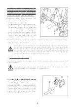
A safety chain (C) is supplied with the
machine to support the PTO shaft (T) when
disconnected to avoid damage or
deterioration due to contact with the
ground.
Fit the chain (C) to hook (U) as shown
in figure opposite.
Содержание EL 100 N
Страница 1: ...ASSEMBLY OPERATOR S MANUAL EL 100 N POWER TILLER N 95458 A GB 12 1999...
Страница 10: ...8...
Страница 18: ...16...


