KTR-STOP
®
M-A-F B-xx
Operating/Assembly instructions
KTR-N
Sheet:
Edition:
445145 EN
19 of 23
1
Please observe protection
note ISO 16016.
Drawn:
2022-12-20 Ka/Wie
Replacing:
Verified:
2022-12-21 Ka
Replaced by:
To ensure the full braking power, both disassembly and assembly have to be performed at
the highest level of purity.
•
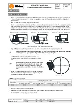
Disassemble the brake, please observe chapter 4.10
Disassembly of brakes.
•
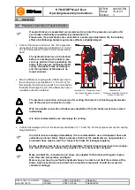
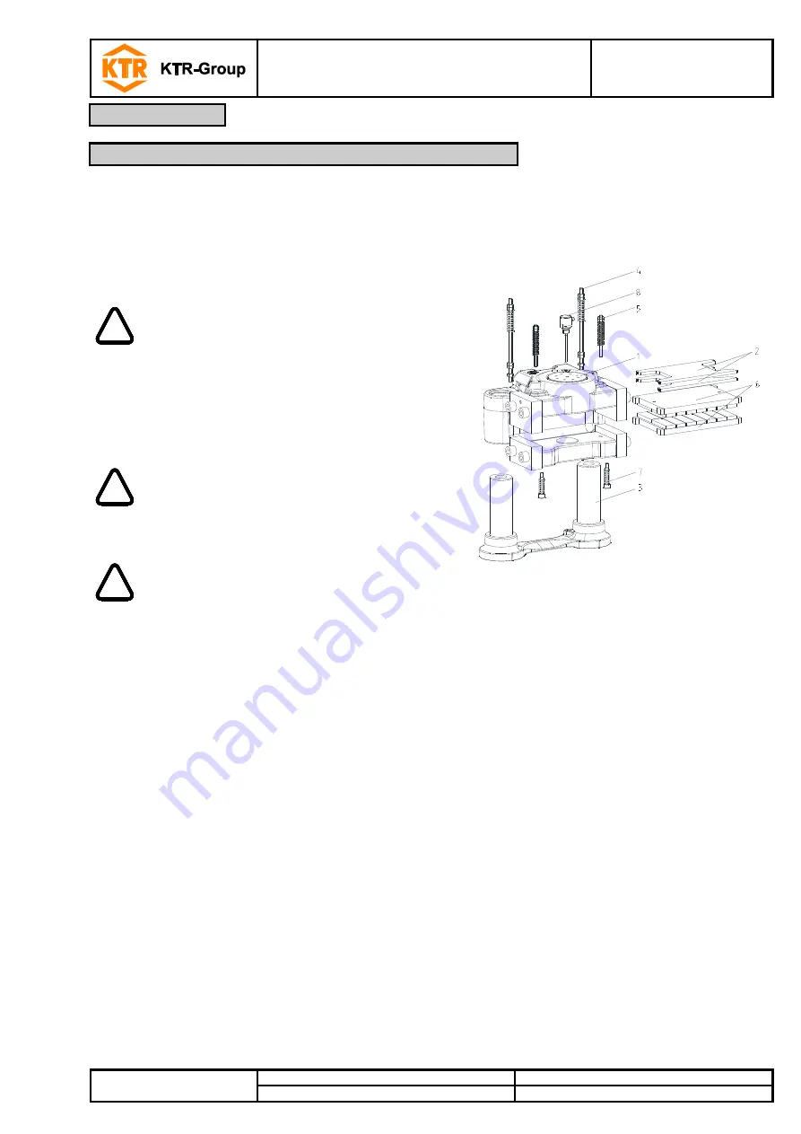
Remove the pad retraction sets (component 5 and 7).
Illustration 17: KTR-STOP
®
M-A-F B-xx
!
Disassemble the pad rectraction sets
carefully since the springs are prestres-
sed.
•
Take out the brake pads (component 6) and the distance
plates (component 2).
•
Each untighten the bottom 3-off hexagon nuts of the
centering system (component 4) and unscrew the pins
(component 4.1) from the base plate (component 3.1).
!
The two hexagon nuts on top of the cen-
tering system (component 4) must not be
disassembled.
•
Remove the brake caliper (component 1) from the guide
pin (component 3.2).
!
Inspect the components/subassemblies 2,
3 and 4 for any kind of damage; it may be
necessary to replace the components.
Afterwards remove dirt, grease and corro-
sion from the components.
•
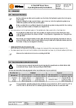
Connect the hydraulics to a pressure port (see illustration 13) of the caliper and make sure that all other
pressure ports are locked by screw plugs.
•
Press the brake piston (component 1.8) carefully out of the brake caliper by using some hydraulic oil.
•
Remove the gasket (component 1.10) and the scraper (component 1.9).
When removing the gaskets and scrapers make sure that the keyways in the caliper are not
damaged.
•
The components have to be cleaned from dirt, grease and corrosion protection. The components can easily be
cleaned by means of solvents. Afterwards dry the components.
5
Maintenance
5.2 Maintenance of the brake / replacement of single parts


