background image


KTR-STOP

®

 M-A-F B-xx 

Operating/Assembly instructions 

KTR-N 
Sheet: 
Edition: 

445145 EN 
1 of 23 


Please observe protection 
note ISO 16016. 

Drawn: 

2022-12-20 Ka/Wie 

Replacing: 


Verified: 

2022-12-21 Ka 

Replaced by: 


KTR-STOP

®

 M-A-F B-xx 


M-A-F B-xx is a brake actuated hydraulically in a floating caliper design serving 
to generate a brake force on a brake disk in order to decelerate a machine's mo-
vement or stop it, respectively, or keep it at standstill. 


Содержание KTR-STOP M-A-F B Series

Страница 1: ...ote ISO 16016 Drawn 2022 12 20 Ka Wie Replacing Verified 2022 12 21 Ka Replaced by KTR STOP M A F B xx M A F B xx is a brake actuated hydraulically in a floating caliper design serving to generate a brake force on a brake disk in order to decelerate a machine s mo vement or stop it respectively or keep it at standstill ...

Страница 2: ...ging 6 3 1 Storage 6 3 2 Transport and packaging 6 4 Assembly 7 4 1 Components of the brake 7 4 2 Preparation of assembly 9 4 3 Brake pads 10 4 4 Assembly of the brake 10 4 5 Setting resetting of the centering system 12 4 6 Pressure connection of a brake 13 4 7 Pressure connection of several brakes 14 4 8 Start up of the brake 15 4 9 Recommendation of fluids to be used 15 4 10 Disassembly of the b...

Страница 3: ...iston surface complete brake in cm2 113 Volume for each brake caliper with 1 mm stroke in cm3 11 3 Max operating pressure in bar 115 Thickness of brake disk 3 in mm 30 40 50 Pressure connection G 1 4 Drain port G 1 8 Floating range on axles towards mounting surface in mm 5 off the mounting surface in mm 10 Min diameter of brake disk ØDA in mm 800 Operating temperature in C 20 to 50 2 The friction ...

Страница 4: ... 21 Ka Replaced by Calculation of braking force braking torque 2 F F c b 2 2 0 D F z M A b b Fb Fc Mb z DA 0 2 Braking power in kN Clamping force in kN Braking torque in kNm Number of brakes Outside diameter of brake disk in m Width of brake pad in m Calculation of brake disk Illustration 2 Assembly of brake Table 2 Calculation of brake disk DC max DA 420 Dav DA 200 1 Technical data ...

Страница 5: ...erating assembly instructions are part of your product Please store them carefully The copyright for these operating assembly instructions remains with KTR S T O P Warning of personal injury This symbol indicates notes which may contribute to pre venting bodily injuries or serious bodily injuries that may result in death Warning of product damages This symbol indicates notes which may contribute t...

Страница 6: ...ata see chapter 1 Unauthorized modifications on the brake design are not admissible We will not assume liability for any damage that may arise In the interest of further development we reserve the right for technical modifications The brake type M A F B xx described in here corresponds to the state of the art at the time of printing of these operating assembly instructions The brake is delivered i...

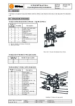
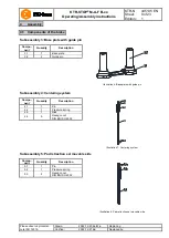
Страница 7: ...e side 6 2 Brake pad 7 2 Pad retraction set on fixed side 8 1 2 Sensor 1 Number depends on thickness of brake disk 2 Optionally available Illustration 4 Components subassemblies of brake Component 2 Number of the spacer plate Thickness of brake disk Number of spacer plates 30 2 40 1 50 Subassembly 1 Caliper with components Compo nent Quantity Description Illustration 5 Caliper with components 1 1 ...

Страница 8: ...Illustration 6 Base plate with guide pin 3 1 1 Base plate 3 2 2 Guide pin Subassembly 4 Centering system Compo nent Quantity Description Illustration 7 Centering system 4 1 1 Pin 4 2 1 Pressure spring 4 3 1 Disk 4 4 5 Hexagon nut DIN EN ISO 4032 Subassembly 5 Pad retraction set movable side Compo nent Quantity Description Illustration 8 Pad retraction set movable side 5 1 1 Pin 5 2 1 Pressure spri...

Страница 9: ...e brake as well as the brake disk have to be inspected for dimensional accuracy For that purpose investigate the connection dimensions connection surfaces and tolerances as specified in the drawing see illustrations 1 to 3 and table 3 Clean and degrease the brake disk and mounting surfaces Dirt can easily be removed by means of solvents The connection between connection surface and brake is define...

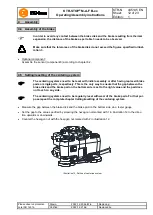
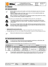
Страница 10: ...roper lifting equipment The brake is mainly selected for mounting on vertically aligned brake disks see illustration 3 With horizontally aligned brake disks see illustration 1 the brake may only be aligned upright There are M12 threads in the pad retainer to fasten an eye bolt serving to use lifting tools The eye bolt is to be dismounted after assembly of the brake and stored in a safe place In or...

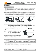
Страница 11: ...Illustration 10 Setting of pad retraction set movable side Repeat this process with the pad retraction set on the moveable side of caliper component 5 Secure the screw connection component 5 1 and 7 1 at the brake pad additionally against working loose e g conglutinating with Loctite average strength Insert the brake in the correct position towards the connection plate Hand tighten the brake via t...

Страница 12: ...ng replaced brake pads or single parts respectively This is the only way to ensure that the gap between the brake disk and the brake pad on the bottom side is set to the right value and the pad does not touch on any side The centering systems need to be regularly reset with wear of the brake pads For that pur pose repeat the complete chapter Setting resetting of the centering system Measure the ga...

Страница 13: ...g system make use of the pressure connection on top It is not recommended to use steel plugs for venting Connect the leakage oil line to the brake see illustration 13 and 14 For that purpose remove the sealing plug beforehand In order to locate a leakage immediately it is recommended to use a transparent hose and collection container Since higher pressures 5 bars at the maximum are not generated a...

Страница 14: ...onger ensured Illustration 15 Pressure connec tion of several brakes in paral lel Illustration 16 Pressure connection of several brakes in a series The pressure connection on top serves for venting the brake For a flushing system make use of the pressure connection on top With the parallel connection of brakes see illustration 15 each brake needs to be vented individually It is not recommended to ...

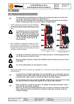
Страница 15: ...uries of your hands Before every maintenance operation make sure that the brake is fully secured against activating Applying with the use of a sensor only Mount the sensor component 8 according to chapter 6 2 instead of the screw plug component 1 11 The brake pads have to be run in on the surface of the brake disk to achieve the nominal coefficient of friction Observe the instructions for run in a...

Страница 16: ...enance operations on the hydraulic system In order to ensure a smooth operation of the overall system the maintenance operations on the hydraulic system inspection of level and degree of dirt replacing the hydraulic liquid resp filter elements etc have to be perfor med as per the manufacturer s operating instructions The system has to be flushed resp vented after each replacement of the hydraulic ...

Страница 17: ...dual waste Sensors Electric components have to be treated as electric waste Hydraulic oil Hydraulic oils have to be collected in suitable tanks and disposed of by a waste disposal company Brake pads having a balance of pad height of less than 2 mm have to be replaced by return Make sure that the entire brake system is depressurized S T O P Parts released or falling down may cause injury to persons...

Страница 18: ...g component 7 2 onto the pin component 7 1 Screw the pin with the pressure spring into the brake pad against a stop Repeat this process with the pad retraction set on the moveable side of caliper component 5 Secure the screw connection component 5 1 and 7 1 at the brake pad additionally against working loose e g conglutinating with Loctite average strength Repeat chapter 4 5 Setting resetting of t...

Страница 19: ...he two hexagon nuts on top of the cen tering system component 4 must not be disassembled Remove the brake caliper component 1 from the guide pin component 3 2 Inspect the components subassemblies 2 3 and 4 for any kind of damage it may be necessary to replace the components Afterwards remove dirt grease and corro sion from the components Connect the hydraulics to a pressure port see illustration 1...

Страница 20: ...ss is no lon ger ensured due to wear and damages Grease the gaskets and scrapers with hydraulic oil see illustration 20 Oils and greases containing molybdenum disulphite or zinc sulphite additives must not be used Illustration 19 Assembly of gasket and scraper Illustration 20 Inspect the surfaces of the brake piston and the hole of the brake caliper to make sure that they are neither scratched nor...

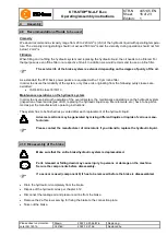
Страница 21: ...value specified by screwing the hexagon nut marked with 1 in illustration 21 in the direc tion upwards or downwards Counter the hexagon nut with the hexagon nut marked with 2 in illustration 21 Repeat chapters 4 2 to 4 8 Illustration 21 Setting of centering system KTR STOP M A F B xx is a low maintenance brake We recommend to perform a visual inspection and an ope rational testing on the brake at ...

Страница 22: ...n no wear off pre wear 2 Switch position 0 unlocked 1 locked The sensor only shows the wear status reliably when the brake is activated locked If the brake is not activated unlocked a statement about the condition of wear cannot be given The wear of the brake pad is only measured when the brake is activated When the brake is not activated there is no signal Pre wear is indicated as soon as the bra...

Страница 23: ...ue M12 hand tight Length of cable 5 m 10 m or 15 m Material of cable PUR Dimension of cable 5 0 34 mm2 Illustration 24 Pin assignment of plug in connection Remove the screw plug component 1 11 from the brake caliper with piston cover component 1 1 Screw the sensor component 8 hand tight into the brake for the time being see illustration 25 Tighten the sensor at the tightening torque TA 20 Nm Provi...

Отзывы: