7
5.5 Connecting the piping
Never use the pump itself as an anchorage point
for the piping.
The pump must not be subjected to any pipeline forces and
moments (for example by torsion, thermal expansion).
Suction lift lines shall be laid with a rising slope towards the
pump and suction head lines with a downward slope towards
the pump. The pipelines shall be anchored in close proximity
to the pump and connected without transmitting any stresses
or strains.
With short pipelines, the nominal diameters should be at least
equal to the nominal diameters of the pump nozzles. For long
pipelines, the most economical nominal diameter has to be
determined from case to case.
Adapters to larger diameters should have a diffuser angle of
approx. 8 in order to avoid any increase in pressure losses.
It is recommended to install check and shut-off elements in
the system, depending on the type of plant and pump.
Thermal expansions of the pipelines must be compensated by
appropriate measures so as not to impose any extra loads on
the pump exceeding the permissible pipeline forces and
moments.
An excessive, impermissible increase in the pipeline
forces may cause leaks on the pump where the medium
handled can escape into the atmosphere.
Danger of life when hot media are handled!
The flange covers on the pump suction and discharge nozzles
must be removed prior to installation in the piping.
Before commissioning new installations thoroughly clean,
flush and blow through all vessels, pipelines and connec-
tions.Often welding beads, scale and other impurities only
come off after a certain period of operation. Fit a strainer in the
suction line to prevent them from entering the pump. The total
cross-section of the holes in the strainer shall be three times
the cross-section of the pipeline in order to avoid excessive
pressure loss across the strainer due to clogging. Conical
strainers with laid-in wire mesh having a mesh width of 0.5
mm and a wire diameter of 0.25 mm, of corrosion-resistant
material, shall be used.
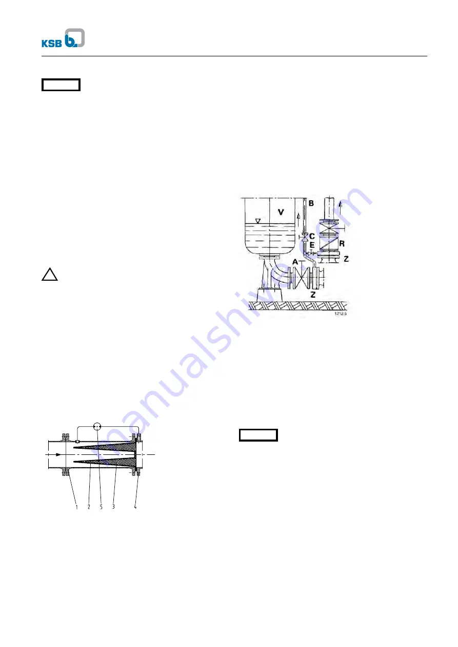
1 Strainer housing
2 Fine screen
3 Perforated plate
4 Pump suction nozzle
5 Differential pressure gauge
Fig. 5.5-1 Conical strainer for the suction line
5.5.1 Auxiliary connections
The dimensions and location of the auxiliary connection (drain
line) are indicated on the general arrangement drawing or pip-
ing layout.
5.5.2 Vacuum balance line
Where liquid has to be pumped out of a vessel under vacuum,
it is advisable to install a vacuum balance line. This line shall
have a nominal diameter of at least 25 mm and must be
arranged to lead into the vessel at a point above the highest
permissible liquid level.
An additional pipeline fitted with a shut-off valve – from the
pump discharge nozzle to the balance line – facilitates venting
of the pump before start-up.
A Main shut-off valve
B Vacuum balance line
C Shut-off valve
E Vacuum-tight shut-off valve
R Swing check valve
V Vessel under vacuum
Z Intermediate flange
Fig. 5.5-2 Suction line and vacuum balance line
5.6 Final check
Check the integrity and proper functioning of all
connections.
5.7 Connection to power supply
Connection to the power supply must be effected by a trained
electrician only.
The applicable DIN VDE regulations 0100 and, for explosion-
proof units, 0165 must be complied with.
Check available mains voltage against the data on the motor
rating plate and select appropriate start-up method.
All connections shall be effected in accordance with the
technical specifications issued by the local energy sup-
ply company.
We strongly recommend to use a motor protection device. DIN
VDE 0170/0171 stipulates that explosion-proof motors, type of
protection IP 54, increased safety Ex EEx, temperature class
T3, must always be connected via a motor protection switch.
121
1:
19/
4
Etabloc
!
Caution
Caution
Содержание Etabloc
Страница 1: ...Operating Instructions Close coupled Pumps Etabloc...
Страница 2: ......
Страница 19: ......
Страница 20: ...Etabloc Gartone Press Tel 011 440 6126 29 6 2004 Subject to technical modification without prior notice...


