7.2.2.2 Grease quality / grease change
The bearings are packed with high-quality lithium-soap
grease. Under normal conditions the grease-lubricated bear-
ings will run for 15,000 operating hours or 2 years. Under
unfavourable operating conditions, e.g. high room tempera-
ture, high atmospheric humidity, dust-laden air, aggressive
industrial atmosphere etc., the bearings shall be checked
earlier and cleaned and re-lubricated, if required.
Use a high-quality lithium-soap grease, free of resin and acid,
not liable to crumble and with good rust-preventive charac-
teristics. The grease should have a penetration number
between 2 and 3, corresponding to a worked penetration
between 220 and 295 mm/10. Its drop point must not be
below 175ºC. The bearing cavities must only be half-filled
with grease.
If required, the bearings may be lubricated with greases of
other soap bases. Since greases of differing soap bases must
not be mixed, the bearings must be thoroughly cleaned
beforehand. The re-lubrication intervals required must then
be adjusted to the greases used.
Please observe the local laws applicable to the
disposal of such substances!
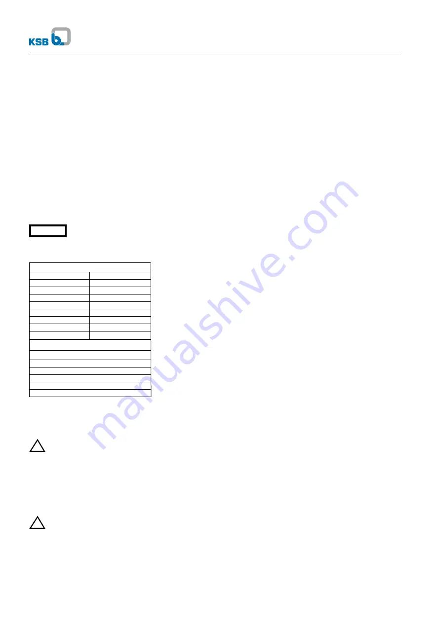
7.2.2.3 Deep-groove ball bearings/ Lubricant quantity for
KSB IEC motor
Deep-groove ball bearings to DIN 625
Code Grease
g
6004 C3
2
6205 C3
3
6206 C3
4
6208 C3
6
6209 C3
7
6210 C3
7
6212 C3
7
6213 C3
11
- for KSB motor with extended shaft
Deep-groove ball bearings to DIN 625
Code
6305 C3
6306 C3
6308 C3
6309 C3
Closed bearings greased for life (2 Z or 2 RS bearings) can-
not be washed out and refilled. They will have to be replaced
by new ones.
7.3 Drainage / disposal
If the pump was used for handling liquids posing health
hazards, see to it that there is no risk to persons or the
environment when draining the medium. All relevant laws
must be heeded. If required, wear safety clothing and a pro-
tective mask!
The flushing liquid used and any liquid residues in the pump
must be properly collected and disposed of without posing
any risk to persons or the environment.
7.4 Dismantling
Before dismantling the pump, secure it so as to make
sure it cannot be switched on accidentally. The shut-off
valves in the suction and discharge lines must be closed.
The pump must have cooled down to ambient temperature,
pump pressure must have been released and the pump must
have been drained.
Dismantling and reassembly must always be carried out in
accordance with the relevant exploded view.
7.4.1 Fundamental instructions and recommendations
Repair and maintenance work to the pump must only be car-
ried out by specially trained personnel, using original spare
parts
(see 2.7).
Observe the safety regulations laid down in section 7.1.
Any work on the motor shall be governed by the specifi-
cations and regulations of the respective motor supplier.
Dismantling and reassembly must always be carried out
in the sequence shown in the relevant exploded views on
pages 16 to 23.
In the case of damage or pump failure please contact our
nearest customer service centre.
For customer service centres please refer to the attached list
of addresses.
7.4.2 Preparations for dismantling
1
Interrupt power supply.
2
Dismantling the complete unit:
2.1 Disconnect the motor from the power supply.
2.2 Unbolt the discharge and suction nozzle from the piping.
2.3 Depending on the pump /motor size, unscrew the bolts
that fix the support foot and/or motor foot to the founda-
tion.
2.4 Remove the complete unit from the piping.
3
The pump casing remains in the piping during disman-
tling.
3.1 Disconnect the motor from the power supply.
3.2 Unscrew hex. nuts 920.2/.3/.4.
3.3 Depending on the pump /motor size, unscrew the bolts
that fix the support foot and/or motor foot to the founda-
tion.
3.4 Withdraw the complete rotating assembly with the motor
from the pump casing.
4 Pump (Etabloc-N only) remains in the piping,motor is
removed
4.1 Disconnect the motor from the power supply.
4.2 Press cover plates 68-3 slightly together and remove
from drive lantern 341.
4.3 Undo hex. nuts 920.5.
4.4 Undo hex. head bolts 901.3.
4.5 Insert both lock washers 931 into the groove in shaft 210.
4.6 Tighten hex. head bolts 901.
4.7 Remove the motor.
After a prolonged period of operation the individual compo-
nents may be hard to pull off the shaft. If this is the case, use
a brand name penetrating agent and/or - if possible - an
appropriate pull-off device.
Under no circumstances use force.
7.4.3 Pump
Dismantle the pump in the sequence shown in the exploded
views on pages 16 to 23.
7.4.4 Mechanical seal
In order to replace the mechanical seal the pump must be
dismantled.
After removing impeller 230 pull mechanical seal 433 off the
shaft by hand.
Prior to reassembly, clean the shaft sleeve 523 and touch up
score marks or scratches, if any, with a polishing cloth. If the
score marks are still visible, fit a new shaft sleeve. Clean the
seat ring location.
Etabloc
!
!
Caution
10
Содержание Etabloc
Страница 1: ...Operating Instructions Close coupled Pumps Etabloc...
Страница 2: ......
Страница 19: ......
Страница 20: ...Etabloc Gartone Press Tel 011 440 6126 29 6 2004 Subject to technical modification without prior notice...


