Kramer Electronics Ltd.
KIT-400
– Connecting KIT-400
9
Connecting KIT-400
Always switch off the power to each device before connecting it to your
KIT-400
. After
connecting your
KIT-400
, connect its power and then switch on the power to each device.
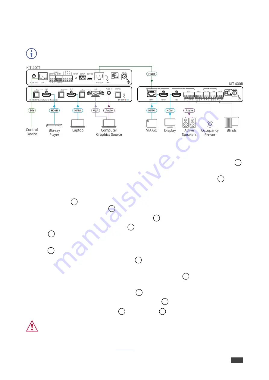
Figure 3: Connecting to the KIT-400
To connect KIT-400 as illustrated in the example in Figure 3:
1. Connect an HDMI source (for example, a Blu-ray player) to the IN 1 HDMI connector
on the
KIT-400T
front panel.
2. Connect an HDMI source (for example, a laptop) to the IN 2 HDMI connector
on the
KIT-400T
front panel.
3. Connect a computer graphics source (for example, a PC) to the IN 3 15-pin HD
connector
and an unbalanced audio source (for example, the PC audio output) to the
AUDIO IN 3.5mm mini jack
on the
KIT-400T
front panel.
4. Connect a control device to the LAN RJ-45 port
on the
KIT-400T
rear panel.
5. Connect the HDBT OUT RJ-45 port
on the
KIT-400T
to the HDBT INPUT RJ-45 port
on the
KIT-400R
.
6. Connect an HDMI source (for example, Kramer
VIA GO
) to the HDMI INPUT connector
on the
KIT-400R
.
7. Connect the HDMI OUTPUT connector
on the
KIT-400R
to an HDMI acceptor (for
example, a display).
8. Connect the AUDIO OUTPUT 5-pin terminal block connector
on the
KIT-400R
to a
balanced stereo audio source (for example, Kramer active speakers).
9. Connect the REMOTE TOGGLE switch
to an occupancy sensor.
10. Connect the RELAY 3-pin terminal block connector
to the room blinds.
11. Set POC switches on
KIT-400T
and
KIT-400R
to ON.
Failure to use PoC and power connector correctly may destroy the devices!
12. Connect the power adapter to one of the devices (
KIT-400T
or
KIT-400R
) and to the
mains electricity (not shown in
2
4
6
7
11
18
32
33
34
35
36
39
20
40


