FS-107
3-6
1
O
UTLINE
2
UNIT EXPLANA
TION
3
D
IS./ASSEMBL
Y
[6]
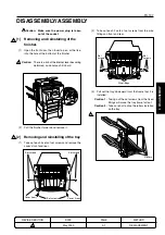
Removing and reinstalling the
stapler unit
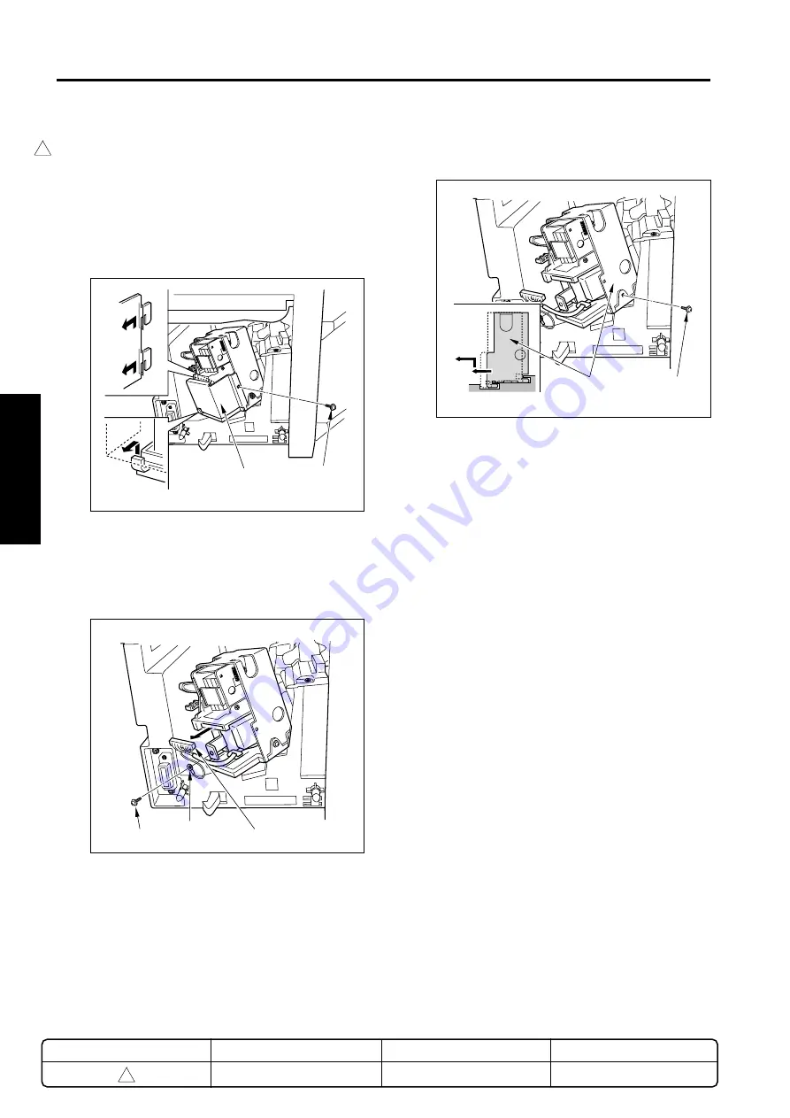
(1)
Remove the finisher from the main unit.
(2)
Take out the fixing plates of the plate affixing the
stapler unit, from the rear of the finisher unit.
(3)
Slide the plate and remove.
Caution:
When reinstalling the plate, be sure to
insert the plate into the insides of the
hooks.
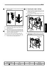
(4)
Take out the connector and 1 grounding screw
from the stapler unit.
Stapler units
Set screw
Plate
Set screw
Grounding screw
Connector
Ground
Hook
(5)
Take out the set screw from the unit saddle, slide
out and remove the stapler unit.
(6)
Install by reversing the removal procedure.
METHOD
REPLACEMENT
PAGE
3-6
DATE
May 2000
REVISED EDITION
1
1
Содержание FS-107
Страница 1: ...KONICA CORPORATION TECHNOLOGY SUPPORT CENTER TOKYO JAPAN SERVICE HANDBOOK FS 107 2001 02 Ver 3 0...
Страница 2: ...CN26NF1780 KONICA CORPORATION COPYRIGHT 2001...
Страница 4: ...Blank page 2 1 OUTLINE 2 UNIT EXPLANATION 3 DIS ASSEMBLY...
Страница 5: ...1 OUTLINE 2 UNIT EXPLANATION 3 DIS ASSEMBLY OUTLINE 1...
Страница 6: ...Blank page 2 1 OUTLINE 2 UNIT EXPLANATION 3 DIS ASSEMBLY...
Страница 14: ...Blank page 2 1 OUTLINE 2 UNIT EXPLANATION 3 DIS ASSEMBLY...
Страница 15: ...1 1 OUTLINE 2 UNIT EXPLANATION 3 DIS ASSEMBLY UNIT EXPLANATION 2...
Страница 16: ...Blank page 2 1 OUTLINE 2 UNIT EXPLANATION 3 DIS ASSEMBLY...
Страница 32: ...Blank page 2 1 OUTLINE 2 UNIT EXPLANATION 3 DIS ASSEMBLY...
Страница 33: ...1 OUTLINE 2 UNIT EXPLANATION 3 DIS ASSEMBLY DISASSEMBLY ASSEMBLY 3...

