FS-107
3-4
1
O
UTLINE
2
UNIT EXPLANA
TION
3
D
IS./ASSEMBL
Y
[4]
Removing and reinstalling of the
up/down wire
(1)
Take out the 3 sets of set screws and remove the
front cover and rear cover.
(2)
Remove the 2 set screws from each of the front and
rear wires, and then remove the tray unit.
Caution:
Perform the removing/installing of the front
up/down wire before performing the
removing/installing of the rear up/down
wire.
(3)
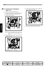
Loosen the 2 set screws and release the pulley
tension plate (front) from its fixed position.
(4)
Remove the E-ring of the lower pulley (front).
(5)
Remove the lower pulley (front) and remove the up/
down wire (front).
(6)
Attach the metallic ball of the up/down wire on the
inner surface of the lower pulley (front), and insert
into the shaft. The metallic ball to be set is the one
longer from the wire fitting.
Also, check to see if the gear position at which the
pulley is installed is in line with the opposite side (rear).
Set screws
Pulley tension
plate
Caution:
Ensure that the pulley installation gear is
horizontal with respect to the casing.
(7)
Wind the up/down wire once around the lower
pulley (front) counter-clockwise, and string it to the
upper pulley (front).
(8)
Down the up/down wire strung to the upper pulley
(front) to the lower pulley and wind it around 4 times
counter-clockwise, and attach the metallic ball on
the end to the side of the lower pulley (front).
(9)
Attach the E-ring and affix the lower pulley (front).
(10) Fasten the 2 set screws while pulling up the pulley
tension plate (front), applying 3kg tension.
Caution:
Apply the required amount of tension at
the time of affixing the pulley tension plate
by using such devises as a tension gauge.
Required value: 3kg
1
1
1
Pulley installation gear
METHOD
REPLACEMENT
PAGE
3-4
DATE
May 2000
REVISED EDITION
1
1
1
Содержание FS-107
Страница 1: ...KONICA CORPORATION TECHNOLOGY SUPPORT CENTER TOKYO JAPAN SERVICE HANDBOOK FS 107 2001 02 Ver 3 0...
Страница 2: ...CN26NF1780 KONICA CORPORATION COPYRIGHT 2001...
Страница 4: ...Blank page 2 1 OUTLINE 2 UNIT EXPLANATION 3 DIS ASSEMBLY...
Страница 5: ...1 OUTLINE 2 UNIT EXPLANATION 3 DIS ASSEMBLY OUTLINE 1...
Страница 6: ...Blank page 2 1 OUTLINE 2 UNIT EXPLANATION 3 DIS ASSEMBLY...
Страница 14: ...Blank page 2 1 OUTLINE 2 UNIT EXPLANATION 3 DIS ASSEMBLY...
Страница 15: ...1 1 OUTLINE 2 UNIT EXPLANATION 3 DIS ASSEMBLY UNIT EXPLANATION 2...
Страница 16: ...Blank page 2 1 OUTLINE 2 UNIT EXPLANATION 3 DIS ASSEMBLY...
Страница 32: ...Blank page 2 1 OUTLINE 2 UNIT EXPLANATION 3 DIS ASSEMBLY...
Страница 33: ...1 OUTLINE 2 UNIT EXPLANATION 3 DIS ASSEMBLY DISASSEMBLY ASSEMBLY 3...


