FS-107
2-9
1
O
UTLINE
2
UNIT EXPLANA
TION
3
DIS./ASSEMBL
Y
[3]
Paper alignment control
PS709
5VDC
PS709
SGND
PS702
5VDC
PS702
SGND
PS710
5VDC
PS710
SGND
FS CB
M703
24VDC
24VDC
M703 OUT A
M703 OUT A
M703 OUT B
M703 OUT B
M702
24VDC
24VDC
M702 OUT A
M702 OUT A
M702 OUT B
M702 OUT B
M704
24VDC
24VDC
M704 OUT A
M704 OUT A
M704 OUT B
M704 OUT B
24VDC
24VDC
24VDC
5VDC
5VDC
SGND
SGND
PGND
PGND
PGND
SGND
SGND
M ACK
SGND
S REQ
M RXD
SGND
S ACK
M REQ
SGND
M TXD
MAIN BODY
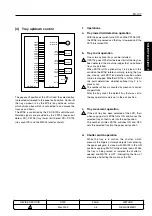
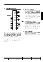
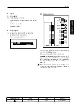
During sorting and stapling, paper exited by the
conveyance section is sent to the alignment section by the
M702 (paper exit motor) reverse direction, then aligned by
the alignment plates driven by the M703 (alignment motor,
(rear)) and the M704 (alignment motor, (front)).
The home position of the alignment plates is detected by
the PS709 (alignment plate detect PS (rear)) and the
PS710 (alignment plate detect PS (front)). The FS CB (FS
control board) controls the M702, M703 and M704. The
related signal are passed to the PS702 (paper entrance
detect PS).
1.
Operations
a.
Normal alignment operation
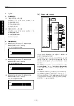
The front and rear alignment plates work in symmetry
to the front and rear based on the center of the
alignment section, alternately aligning and releasing.
To create this symmetrical movement the M703 and
M704 always rotate in opposite directions.
Every five sheets of the conveyed paper are aligned
and sent on to the paper exit section.
The timing of the M703 and M704 are set to the
starting point by the ON/OFF of the PS702 (paper
entrance detect PS).
b.
Offset (shift alignment) operation
The sheets corresponding to odd sets of copies are fed
to the paper exit unit as soon as they have been aligned
normally. (up to 5 sheets are stacked and exited.)
During the alignment operation for even sets of
copies, M703 and M704 rotate in the same direction,
shifting the sheets forward from the center. The
aligned sheets are then sent to the paper exist
unit.(up to 5 sheets are stacked and exited.)
c.
Staple mode operation
In the staple mode, the M703 and M704 are released
after the stapling action is completed.
The ON/OFF timing of the M703 and M704 is set as
the M702 is turned from OFF to ON, and the PS702 is
turned OFF after the specified period of time.
1
METHOD
REPLACEMENT
PAGE
2-9
DATE
May 2000
REVISED EDITION
1
Содержание FS-107
Страница 1: ...KONICA CORPORATION TECHNOLOGY SUPPORT CENTER TOKYO JAPAN SERVICE HANDBOOK FS 107 2001 02 Ver 3 0...
Страница 2: ...CN26NF1780 KONICA CORPORATION COPYRIGHT 2001...
Страница 4: ...Blank page 2 1 OUTLINE 2 UNIT EXPLANATION 3 DIS ASSEMBLY...
Страница 5: ...1 OUTLINE 2 UNIT EXPLANATION 3 DIS ASSEMBLY OUTLINE 1...
Страница 6: ...Blank page 2 1 OUTLINE 2 UNIT EXPLANATION 3 DIS ASSEMBLY...
Страница 14: ...Blank page 2 1 OUTLINE 2 UNIT EXPLANATION 3 DIS ASSEMBLY...
Страница 15: ...1 1 OUTLINE 2 UNIT EXPLANATION 3 DIS ASSEMBLY UNIT EXPLANATION 2...
Страница 16: ...Blank page 2 1 OUTLINE 2 UNIT EXPLANATION 3 DIS ASSEMBLY...
Страница 32: ...Blank page 2 1 OUTLINE 2 UNIT EXPLANATION 3 DIS ASSEMBLY...
Страница 33: ...1 OUTLINE 2 UNIT EXPLANATION 3 DIS ASSEMBLY DISASSEMBLY ASSEMBLY 3...

