FS-107
2-5
1
O
UTLINE
2
UNIT EXPLANA
TION
3
DIS./ASSEMBL
Y
[4]
Tray up/down control
PS703
5VDC
PS703
SGND
PS716
5VDC
PS716
SGND
24VDC
MS702
MS702
PS706
5VDC
PS706
SGND
FS CB
24VDC
24VDC
24VDC
5VDC
5VDC
SGND
SGND
PGND
PGND
PGND
SGND
SGND
M ACK
SGND
S REQ
M RXD
SGND
S ACK
M REQ
SGND
M TXD
MAIN BODY
M706
M706 DRIVE 1
M706 DRIVE 2
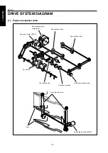
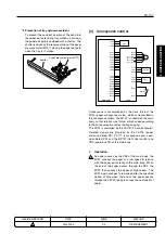
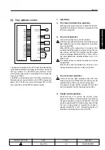
The paper exit position of the FS is fixed, the selected tray
is elevated or lowered to the paper exit position. Control of
the tray up/down is by the M706 (tray up/down motor)
which drives wires which is connected to and moves the
trays up and down.
The M706 is controlled by the FS CB (FS control board).
Related signals are provided by the PS703 (paper exit
detect PS), PS706 (tray lower limit detect PS), PS716
(tray count PS) and the MS702 (shutter switch).
1.
Operations
a.
Tray lower limit detection operation
With the power swich turnd ON, and the PS706 OFF,
the M706 is reversed and the tray is lowered until the
PS706 is turned ON.
b.
Tray count operation
One or two optional trays can be installed.
If PS716 goes OFF after the lower limit of the tray has
been detected, the machine judges that no optional
trays are installed.
When PS716 is ON, optional tray 1 is in place; in this
condition the M706 rotates normally, raising the tray
one step up until PS716’s detection position where
motion is stopped. Whether PS716 is ON or OFF at
this point determines whether optional tray 2 is in
place or not.
The number of trays is counted by means of a series
of operations.
After the tray count, the default tray that was set in
the key operator mode is set in the exit position.
c.
Tray movement operation
If the exit tray has been selected at the LCD, then
when copying starts M706 turns ON and moves the
selected tray so that it sets into the exit position.
The number of times PS703 switches ON and OFF
sets the selected tray into the paper exit position.
d.
Shutter switch operation
While the tray is in motion, the shutter, which
prevents the fingers or foreign objects from entering
the paper exit gate, is closed, with MS702 in the ON
position supplying 24VDC to the various loads. While
the tray is being raised or lowered the shutter is
opened and MS702 is OFF, interrupting the flow of
electricity and halting the motion of the FS.
1
1
1
METHOD
REPLACEMENT
PAGE
2-5
DATE
May 2000
REVISED EDITION
1
Содержание FS-107
Страница 1: ...KONICA CORPORATION TECHNOLOGY SUPPORT CENTER TOKYO JAPAN SERVICE HANDBOOK FS 107 2001 02 Ver 3 0...
Страница 2: ...CN26NF1780 KONICA CORPORATION COPYRIGHT 2001...
Страница 4: ...Blank page 2 1 OUTLINE 2 UNIT EXPLANATION 3 DIS ASSEMBLY...
Страница 5: ...1 OUTLINE 2 UNIT EXPLANATION 3 DIS ASSEMBLY OUTLINE 1...
Страница 6: ...Blank page 2 1 OUTLINE 2 UNIT EXPLANATION 3 DIS ASSEMBLY...
Страница 14: ...Blank page 2 1 OUTLINE 2 UNIT EXPLANATION 3 DIS ASSEMBLY...
Страница 15: ...1 1 OUTLINE 2 UNIT EXPLANATION 3 DIS ASSEMBLY UNIT EXPLANATION 2...
Страница 16: ...Blank page 2 1 OUTLINE 2 UNIT EXPLANATION 3 DIS ASSEMBLY...
Страница 32: ...Blank page 2 1 OUTLINE 2 UNIT EXPLANATION 3 DIS ASSEMBLY...
Страница 33: ...1 OUTLINE 2 UNIT EXPLANATION 3 DIS ASSEMBLY DISASSEMBLY ASSEMBLY 3...

