FS-107
3-3
1
OUTLINE
2
UNIT EXPLANA
TION
3
D
IS./ASSEMBL
Y
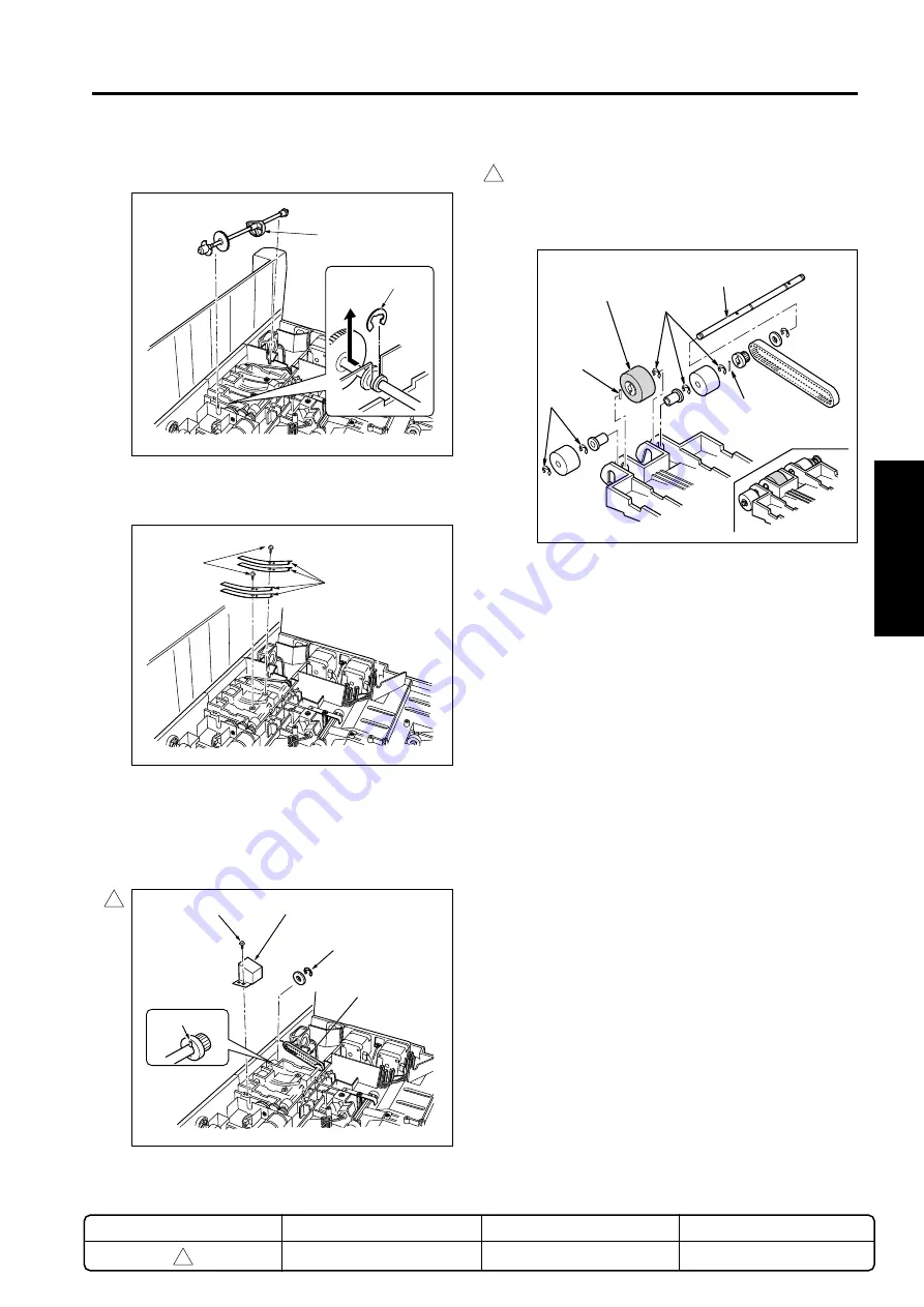
Plate spring
Set screws
Plate
Set screw
E-ring
Belt
(4)
Remove the E-ring and remove the cam shaft.
(5)
Take out the 2 sets of set screws and remove the
set of 2 plate springs.
(6)
Take out 1 set screw and remove the plate.
(7)
Remove the E-ring that affixes the belt gear, slide
the gear and remove the belt.
Caution:
Be careful to not drop the pin inside the
gear.
E-rings
Shaft
E-rings
Pin
Paper exit
roller/A
Pin
(8)
Remove the 5 E-rings and pull out the shaft from
the paper exit roller/A.
Caution:
Be careful to not drop the pin inside the
paper exit roller/A.
(9)
Replace the paper exit roller/A.
(10) Install by reversing the removal procedure.
1
1
METHOD
REPLACEMENT
PAGE
3-3
DATE
May 2000
REVISED EDITION
1
Pin
Shaft
E-ring
Содержание FS-107
Страница 1: ...KONICA CORPORATION TECHNOLOGY SUPPORT CENTER TOKYO JAPAN SERVICE HANDBOOK FS 107 2001 02 Ver 3 0...
Страница 2: ...CN26NF1780 KONICA CORPORATION COPYRIGHT 2001...
Страница 4: ...Blank page 2 1 OUTLINE 2 UNIT EXPLANATION 3 DIS ASSEMBLY...
Страница 5: ...1 OUTLINE 2 UNIT EXPLANATION 3 DIS ASSEMBLY OUTLINE 1...
Страница 6: ...Blank page 2 1 OUTLINE 2 UNIT EXPLANATION 3 DIS ASSEMBLY...
Страница 14: ...Blank page 2 1 OUTLINE 2 UNIT EXPLANATION 3 DIS ASSEMBLY...
Страница 15: ...1 1 OUTLINE 2 UNIT EXPLANATION 3 DIS ASSEMBLY UNIT EXPLANATION 2...
Страница 16: ...Blank page 2 1 OUTLINE 2 UNIT EXPLANATION 3 DIS ASSEMBLY...
Страница 32: ...Blank page 2 1 OUTLINE 2 UNIT EXPLANATION 3 DIS ASSEMBLY...
Страница 33: ...1 OUTLINE 2 UNIT EXPLANATION 3 DIS ASSEMBLY DISASSEMBLY ASSEMBLY 3...

