401027/B
51
2
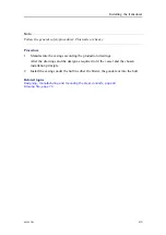
Lift the transducer up into its location.
Check the orientation according to the individual requirement.
3
Pull out the transducer cable, and guide them out through the side of the mounting
frame
4
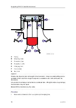
Place the transducer modules into the frames and fasten them the clamping bars to
the stay rods.
The clamping bars are fastened to the stay rods on the mounting frames by M10
bolts with self lock treads. Bolts, clamping bars and stay rods are included with the
mounting frames.
Apply Loctite 242 to secure the bolts.Use torque approximately: 42 Nm.
5
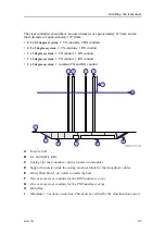
Mount the next transducer module next to the previous. (applicable for 0.5 degree
transducer array).
The gap between the individual modules is determined by the mounting frame.
6
Check that the transducer cables pass through the casing in such a way that they
are not exposed to wear and tear. Secure as required.
The minimum bending radius for the transducer cables is 85mm.
7
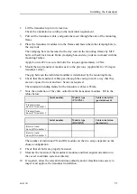
Note the orientation of the cable outlet from the transducer modules. Fill in the
tables below.
Serial number
Module type
(TX1/TX2)
Cable orientation
(port/starboard)
Transmit trans-
ducer (TX) number 1
Transmit trans-
ducer (TX) number 2
Serial number
Module type
(RX1/RX2)
Cable orientation
(bow/astern)
Receive trans-
ducer (RX) number 1
Receive trans-
ducer (RX) number 2
The number of individual TX and RX modules in the two arrays depends on the
chosen configuration.
8
Check that all bolts are properly fastened.
9
Measure the location of the transducer modules and their angular orientation in
the vessel coordinate system accurately.
10
If required, allow the relevant maritime authority and/or classification society to
inspect and approve the transducer installation.
Содержание EM 712
Страница 1: ...401027 B June 2018 Kongsberg Maritime AS Kongsberg EM 712 Multibeam echo sounder Installation manual ...
Страница 68: ...68 401027 B Processing Unit Topics CBMF board dip switch setting page 69 Kongsberg EM 712 Installation manual ...
Страница 71: ...401027 B 71 216148 EM 712 Transducer TX1 dimensions Drawing file ...
Страница 72: ...72 401027 B Kongsberg EM 712 Installation manual ...
Страница 73: ...401027 B 73 221048 EM 712 Transducer TX2 dimensions Drawing file ...
Страница 74: ...74 401027 B Kongsberg EM 712 Installation manual ...
Страница 75: ...401027 B 75 219621 EM 712 Transducer RX1 dimensions Drawing file ...
Страница 76: ...76 401027 B Kongsberg EM 712 Installation manual ...
Страница 77: ...401027 B 77 216146 EM 712 Transducer RX2 dimensions Drawing file ...
Страница 78: ...78 401027 B Kongsberg EM 712 Installation manual ...
Страница 79: ...401027 B 79 223137 EM 712 Transducer mounting frame 0 5 degrees Drawing file ...
Страница 80: ...80 401027 B Kongsberg EM 712 Installation manual ...
Страница 81: ...401027 B 81 223139 EM 712 Transducer mounting frame 1 degree Drawing file ...
Страница 82: ...82 401027 B Kongsberg EM 712 Installation manual ...
Страница 83: ...401027 B 83 223273 EM 712 Transducer mounting frame 2 degrees Drawing file ...
Страница 84: ...84 401027 B Kongsberg EM 712 Installation manual ...
Страница 85: ...401027 B 85 317812 EM 712 Casing w mounting frame 0 5 degrees Drawing file ...
Страница 86: ...86 401027 B 320320 EM 712 Casing w mounting frame 1 degree Kongsberg EM 712 Installation manual ...
Страница 87: ...401027 B 87 375817 EM 712 Combined casing w mounting frame 1 degree Drawing file ...
Страница 88: ...88 401027 B 331369 EM 712 Casing w mounting frame 2 degrees Kongsberg EM 712 Installation manual ...
Страница 89: ...401027 B 89 396402 EM 712 Transmitter Unit dimensions Drawing file ...
Страница 90: ...90 401027 B 212984 EM 712 Transmitter Unit mounting bracket Kongsberg EM 712 Installation manual ...
Страница 91: ...401027 B 91 396428 EM 712 Receiver Unit dimensions Drawing file ...
Страница 92: ...92 401027 B 385422 Processing Unit dimensions Kongsberg EM 712 Installation manual ...
Страница 93: ...401027 B 93 378828 Hydrographic Work Station dimensions Drawing file ...
Страница 94: ...94 401027 B Kongsberg EM 712 Installation manual ...
Страница 95: ...401027 B 95 371591 Rack installation kit dimenisons Drawing file ...
Страница 96: ...96 401027 B 370275 Remote Control Unit K REM dimensions Kongsberg EM 712 Installation manual ...
Страница 97: ...401027 B 97 Drawing file ...
Страница 98: ...98 401027 B 373962 Remote Control Unit K REM wiring diagram Kongsberg EM 712 Installation manual ...
Страница 112: ...112 401027 B RX array identification RX2 TX Unit identification 3 2 RX 3 4 2 RX 4 Kongsberg EM 712 Installation manual ...
Страница 163: ...401027 B 163 Certificates IEC 60945 IACS E10 Technical specifications ...
Страница 177: ...401027 B 177 7 Observe the handling rules for transducers Equipment handling ...
Страница 188: ... 2018 Kongsberg Maritime ...


