44
401027/B
Designing, manufacturing and mounting the
steel conduits
Steel conduits are used to protect the transducer cables.
Prerequisites
You must be equipped with a standard set of tools. This tool set must comprise the
normal tools for mechanical tasks. This includes different screwdriver types, pliers,
adjustable spanners etc. Each tool must be provided in various sizes. We recommend
that all tools are demagnetized to protect your equipment. The following specific tools
and items are required for this task:
• All relevant vessel and transducer drawings must be available.
• All relevant work instructions, procedures and standards must be available.
• All relevant drawings have been approved by the classification society.
• The physical location of the transducer has been determined.
• The installation method has been determined.
• The installation angles of the transducer have been defined.
• All relevant personnel (naval architects, designers, skilled shipyard workers) and
tools must be available.
Observe the relevant rules and regulations related to welding. The quality of the welding
is critical to the safety of the vessel. Welding must only be done by a certified welder.
The final installation welds must be approved by the vessel’s national registry, the
corresponding maritime authority and/or classification society.
Context
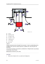
The transducer cables connect through the vessel’s hull using steel conduits. The steel
conduits are welded to the vessel’s hull. The top of each conduit must be closed and
sealed to preserve the watertightness. This can be done with a “Bratberger”, “Roxtec” or
a similar sort of sealing device.
The installation of the steel conduits must be properly planned, and all plans and
drawings must be approved by the vessel’s classification authority. This is always the
yard’s responsibility.
The steel conduits must be designed to fit each individual vessel. They are not included
with the system delivery. The steel conduits must therefore be both provided (or
manufactured) and installed by the installation shipyard. The number of steel conduits
depends on the chosen system configuration and the internal diameter of the conduits.
Kongsberg EM 712 Installation manual
Содержание EM 712
Страница 1: ...401027 B June 2018 Kongsberg Maritime AS Kongsberg EM 712 Multibeam echo sounder Installation manual ...
Страница 68: ...68 401027 B Processing Unit Topics CBMF board dip switch setting page 69 Kongsberg EM 712 Installation manual ...
Страница 71: ...401027 B 71 216148 EM 712 Transducer TX1 dimensions Drawing file ...
Страница 72: ...72 401027 B Kongsberg EM 712 Installation manual ...
Страница 73: ...401027 B 73 221048 EM 712 Transducer TX2 dimensions Drawing file ...
Страница 74: ...74 401027 B Kongsberg EM 712 Installation manual ...
Страница 75: ...401027 B 75 219621 EM 712 Transducer RX1 dimensions Drawing file ...
Страница 76: ...76 401027 B Kongsberg EM 712 Installation manual ...
Страница 77: ...401027 B 77 216146 EM 712 Transducer RX2 dimensions Drawing file ...
Страница 78: ...78 401027 B Kongsberg EM 712 Installation manual ...
Страница 79: ...401027 B 79 223137 EM 712 Transducer mounting frame 0 5 degrees Drawing file ...
Страница 80: ...80 401027 B Kongsberg EM 712 Installation manual ...
Страница 81: ...401027 B 81 223139 EM 712 Transducer mounting frame 1 degree Drawing file ...
Страница 82: ...82 401027 B Kongsberg EM 712 Installation manual ...
Страница 83: ...401027 B 83 223273 EM 712 Transducer mounting frame 2 degrees Drawing file ...
Страница 84: ...84 401027 B Kongsberg EM 712 Installation manual ...
Страница 85: ...401027 B 85 317812 EM 712 Casing w mounting frame 0 5 degrees Drawing file ...
Страница 86: ...86 401027 B 320320 EM 712 Casing w mounting frame 1 degree Kongsberg EM 712 Installation manual ...
Страница 87: ...401027 B 87 375817 EM 712 Combined casing w mounting frame 1 degree Drawing file ...
Страница 88: ...88 401027 B 331369 EM 712 Casing w mounting frame 2 degrees Kongsberg EM 712 Installation manual ...
Страница 89: ...401027 B 89 396402 EM 712 Transmitter Unit dimensions Drawing file ...
Страница 90: ...90 401027 B 212984 EM 712 Transmitter Unit mounting bracket Kongsberg EM 712 Installation manual ...
Страница 91: ...401027 B 91 396428 EM 712 Receiver Unit dimensions Drawing file ...
Страница 92: ...92 401027 B 385422 Processing Unit dimensions Kongsberg EM 712 Installation manual ...
Страница 93: ...401027 B 93 378828 Hydrographic Work Station dimensions Drawing file ...
Страница 94: ...94 401027 B Kongsberg EM 712 Installation manual ...
Страница 95: ...401027 B 95 371591 Rack installation kit dimenisons Drawing file ...
Страница 96: ...96 401027 B 370275 Remote Control Unit K REM dimensions Kongsberg EM 712 Installation manual ...
Страница 97: ...401027 B 97 Drawing file ...
Страница 98: ...98 401027 B 373962 Remote Control Unit K REM wiring diagram Kongsberg EM 712 Installation manual ...
Страница 112: ...112 401027 B RX array identification RX2 TX Unit identification 3 2 RX 3 4 2 RX 4 Kongsberg EM 712 Installation manual ...
Страница 163: ...401027 B 163 Certificates IEC 60945 IACS E10 Technical specifications ...
Страница 177: ...401027 B 177 7 Observe the handling rules for transducers Equipment handling ...
Страница 188: ... 2018 Kongsberg Maritime ...


