15.3
Types C09/CH09 and C13/CH13
15.3.1
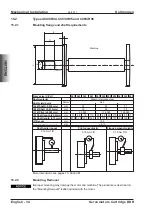
Mounting flange and shaft requirements
Frame size (C/CH)
091
092
093
131
132
133
Shaft material
Cold-rolled steel with 0.3% carbon content
Shaft yield point
N/mm²
380
(A) Ø Shaft (-0.012mm)
mm
60
70
(B) Ø Shaft (-0.012mm)
mm
70
80
(C) Ø Pilot (±0.02mm)
mm
232.94
333.96
(D) Shaft length (±0.13mm)
mm
43.94
88.14
124.71
40.39
83.82
118.62
(E) Shaft length (±1.5mm)
mm
89.92
134.11
170.69
114.05
167.89
253.49
(F) Recess
mm
13.5
17.8
Axial shaft movement
mm
static ±1.5 / dynamic ±0.05
Shaft radial runout
Pilot concentricity
Flange perpendicularity
0.038 mm TIR
0.051 mm TIR
0.051 mm TIR
More dimensions see pages 82 and 83.
15.3.2
Mounting, Removal
Improper mounting may damage the motor and machine.The procedure is described in
the "Mounting/Removal" leaflet included with the motor.
Servomotors Cartridge DDR
English - 35
Kollmorgen
04/2017
Mechanical Installation
ENGLISH
B
C
E
A
F
Machine


