-32-
Fig. 45
Connecting diagram
Trigger switch
Push switch
Pin wheel
switch
Battery terminal
Main PCB ass'y
Tact switch
PCB ass'y
Sensor PCB
ass'y
LD
Yellow
Black
Red
White
Blue
M
Страница 1: ...the orange LED is blinking 8 REPAIR GUIDE 9 1 Precautions on disassembly and reassembly 9 Preparation before disassembly 9 Disassembly and reassembly of the magazine section 10 Disassembly and reasse...
Страница 2: ...f blade guide B too narrow or wide Nail guide groove trouble protrusion or burring of blade guide B and nail support A Step in the nail shank guide groove between blade guide B nail support A and maga...
Страница 3: ...is not for hard wood Deformed output section Check the tips of the pushing lever blade guide nail support and probe for warp deformation and excessive wear Replace defective parts Probe is not set at...
Страница 4: ...ring B and urethane shaft is felt When checking disassemble the magazine referring to page 10 Replace defective parts 5 Nails jam Abnormal nails are used e g bent nails abnormal collation Nails are no...
Страница 5: ...f the magazine section Reassemble blade guide B See page 10 Loose bolts of the output section and magazine section Tighten the bolts at the specified torque Broken or worn out nail support A or spring...
Страница 6: ...tester probes to the points shown in the figure below Make sure the terminals are not electrically connected Set the switch to ON and apply tester probes to the points shown in the figure below Make s...
Страница 7: ...e gear box ass y for breaks Replace defective parts Sensor C trouble Visually check the sensor wires for breaks Replace defective parts Excessively charged compressed air Check the LED lighting patter...
Страница 8: ...seconds Locked by broken gear Locked by worn out piston rack Locked by broken piston bumper Broken wiring Replace defective parts 5 Power switch is automatically turned off after about 9 seconds Exce...
Страница 9: ...motor when detecting two motor rotations 4 Resetting error mode when the orange LED is blinking Error indication Indicated by the orange battery level indicator blinking at intervals of 0 5 second Th...
Страница 10: ...tly with the battery still mounted on the main body the motor may turn unexpectedly and could cause serious injury 1 Removal of the hook Remove the Hook 62 by removing the Nylock Hex Socket Hd Bolts M...
Страница 11: ...2 Nail Support B 93 Spring B 94 and Urethane Shaft 95 from Blade Guide B 88 Remove the Needle Roller D3 x 22 87 Nail Support A 90 and Spring A 89 from Blade Guide B 88 Remove the Tapping Screw W Flang...
Страница 12: ...eedle Roller D3 x 22 87 into the hole of Blade Guide B 88 Insert the Urethane Shaft 95 into Spring B 94 and insert Spring B 94 and Nail Support B 93 into the groove of Blade Guide B 88 NOTE Be sure to...
Страница 13: ...he Adjuster 42 2 Reassembly Reverse the disassembly procedure to reassemble Note the following points CAUTION Adjustment of the Adjuster 42 is required when reassembling Pushing Lever A 44 If adjusted...
Страница 14: ...the power Press the Probe 45 against the 4 5 mm groove of the J 409 push lever gauge Hold down the power switch on the operation switch for 2 seconds and check that the power is not turned on When the...
Страница 15: ...4 move smoothly without any catch Check that the Adjuster 42 does not turn OK Piston Ass y 16 does not contact the J 409 push lever gauge Nailer is vertical 16 86 J 409 push lever gauge 45 NG Piston A...
Страница 16: ...sor C 67 Switch Cable A 55 and Wiring Ass y 60 Remove the two O rings I D 2 5 54 from Switch Cable A 55 Be careful not to lose the O rings Carefully lift the Chamber Base Ass y 11 and Nose 18 to remov...
Страница 17: ...t alignment marks on the Chamber Base Ass y 11 and Cylinder 5 as shown in the figure below before disassembly to indicate the coupling positions 1 Alignment marks 2 3 4 5 6 7 8 9 10 12 13 19 11 20 21...
Страница 18: ...the O ring I D 94 5 7 from the Chamber Base Ass y 11 Push in the Piston Ass y 16 from Blade Guide A 86 side to the Cylinder 5 side to remove it Remove the Hex Socket Hd Bolt M5 71 from the Nose 18 Mo...
Страница 19: ...g 6902VV 30 from the Pin Wheel 28 Remove the Needle Roller D3 31 from the Pin Wheel 28 and then remove the Position Detector 23 Remove the eight Needle Rollers D4 33 and one Needle Roller D4 5 24 from...
Страница 20: ...lignment marks made before disassembly for precise positioning when mounting the Chamber Base Ass y 11 on the Cylinder 5 Slowly tighten the four Nylock Bolts M6 12 to fasten the Chamber Base Ass y 11...
Страница 21: ...to the Cylinder 5 in this order Apply Three Bond TB1342H adhesive in the form of a line circling around the Cylinder 5 two times as shown in Fig 23 Then mount the Special Nut M58 13 Mount Sensor Ass y...
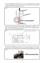
Страница 22: ...sure to mount the Hex Socket Hd Bolt M5 71 to the Nose 18 Insert the Rotor 80 into the Gear Box Ass y 79 and check that the Rotor 80 turns smoothly by hand as shown in Fig 26 NOTE If the Rotor 80 can...
Страница 23: ...ars are properly meshed Push the wires in housing A of Housing Ass y 50 with a flat blade screwdriver being careful not to damage the coating as shown in Fig 28 Black blue and red Sensor C Black blue...
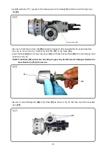
Страница 24: ...hat the terminal of the Wiring Ass y 60 is properly mounted without mismatch and it is slightly movable as shown in Fig 30 Then mount the battery to Housing D E F Ass y 51 and pull it in Y direction a...
Страница 25: ...ds Check that the LED light on the operation panel turns on Next insert a pin punch of 2 4 0 1 mm in diameter and push in Pushing Lever B 40 Hold down the power switch on the operation panel for at le...
Страница 26: ...the brand new Piston Ass y 16 1 Disassembly Remove Housing C 48 magazine ass y and Top Cover 2 to take out the power assembly and Wiring Ass y 60 referring to pages 9 to 15 Replacement of the piston a...
Страница 27: ...Ring D52 19 from the Nose 18 and pull out Bearing Holder 20 and Pin Wheel 28 Remove the Ball Bearing 6000VV 21 from the Pin Wheel 28 Remove the Needle Roller D3 31 from the Pin Wheel 28 Then remove t...
Страница 28: ...Blade Guide A 86 push the Piston Ass y 16 down to the bottom dead point without meshing with the eight Needle Rollers D4 33 and Needle Roller D4 5 24 as shown in Fig 37 Apply about 1 5 g of Isoflex To...
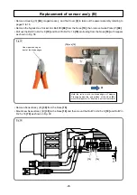
Страница 29: ...truding from the Nose 18 with nippers as shown in Fig 38 Remove Sensor Ass y B 39 from the Nose 18 Mount new Sensor Ass y B 39 to the Nose 18 and then mount the Roll Pin D2 5 x 8 72 and Roll Pin D2 5...
Страница 30: ...6 down to reset the dry fire lockout mechanism 2 Press the Probe 45 against a piece of wood 3 Pull the Trigger 57 Check that the driver blade of the Piston Ass y 16 protrudes from the blade guide 2 Fe...
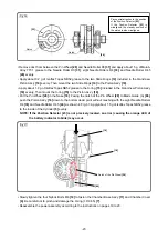
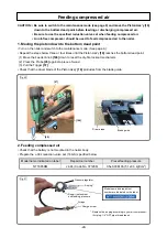
Страница 31: ...pare an air compressor 0 7 MPa or higher and set a delivery pressure of 0 7 to 1 2 MPa See Fig 43 Connect the reduction valve set to the air compressor for at least 10 seconds to feed compressed air S...
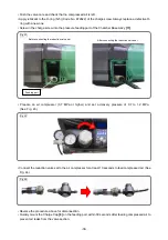
Страница 32: ...d the tip of the Piston Ass y 16 with a caliper and make sure that the distance is 93 9 mm or shorter If the distance is longer than 93 9 mm the Position Detector 23 may be incorrectly mounted Check w...
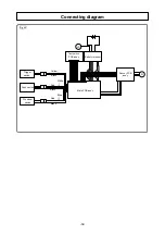
Страница 33: ...32 Fig 45 Connecting diagram Trigger switch Push switch Pin wheel switch Battery terminal Main PCB ass y Tact switch PCB ass y Sensor PCB ass y LD Yellow Black Red Black Black Red White Blue M...
Страница 34: ...shing Stopper B Pushing Stopper Spring Feeder Knob Nail Feeder B Ribbon Spring Nail Feeder Pin Wheel Position Detector Chamber Cover Chamber Base Special Nut M58 O ring x 2 Cylinder Piston Blade Slide...
Страница 35: ...6 37 38 40 41 42 43 44 47 48 49 47 50 56 57 54 55 53 58 64 62 63 80 26 81 82 84 99 100 101 102 85 86 91 97 97 96 98 103 104 105 106 107 83 25 26 67 73 66 68 504 501 505 503 506 79 14 69 70 72 71 78 75...
Страница 36: ...NYLOCK BOLT W FLANGE M5 X 22 2 36 372311 NYLOCK BOLT W FLANGE M4 X 14 2 37 372307 PUSHING LEVER SPRING B 1 38 376289 SPECIAL BOLT M6 1 39 377096 SENSOR ASS Y B 1 INCLUD 40 40 376813 PUSHING LEVER B 1...
Страница 37: ...ORT B 1 94 884534 SPRING B 1 95 886233 URETHANE SHAFT 1 96 372349 PUSHING LEVER STOPPER A 1 97 372350 SPRING 2 98 372351 PUSHING LEVER STOPPER B 1 99 377456 NAIL FEEDER A 1 100 949506 ROLL PIN D4 X 28...