


-17-
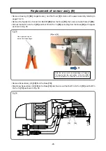
Fig. 16
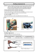
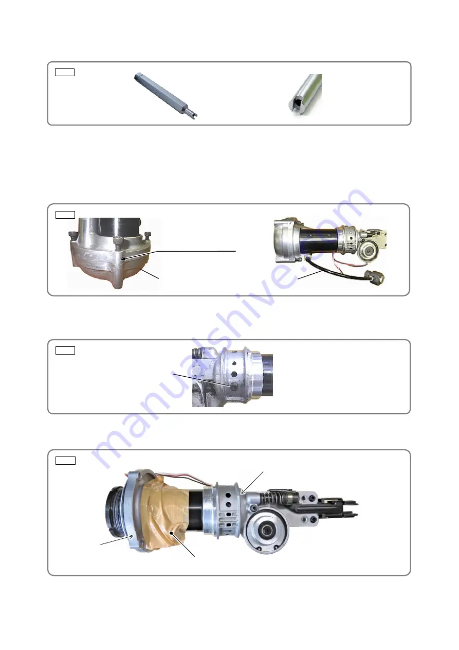
Fig. 19
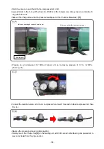
Fig. 17
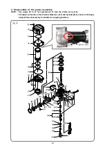
• Remove the valve core from the Chamber Base Ass’y
[11]
by using a commercially available valve core
tool. (See Fig. 16.)
• Remove the four Nylock Bolts M6
[12]
that fasten the Chamber Base Ass’y
[11]
and Chamber Cover
[4]
,
and remove the Chamber Base Ass’y
[11]
.
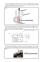
NOTE: If it is difficult to remove the Chamber Base Ass’y [11], temporarily tighten at least two
Nylock Bolts M6 [12] so that the threaded portion can be seen 3.5 mm to 6.5 mm as shown
in Fig. 17. Mount the reduction valve set and feed compressed air to remove the Chamber
Base Ass’y [11].
• Remove the O-ring (I.D 94.5)
[7]
from the Chamber Base Ass’y
[11]
.
• Push in the Piston Ass'y
[16]
from Blade Guide (A)
[86]
side to the Cylinder
[5]
side to remove it.
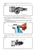
• Remove the Hex. Socket Hd. Bolt M5
[71]
from the Nose
[18]
.
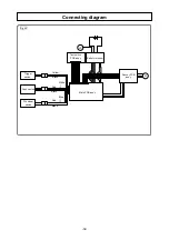
• Move the Chamber Base Ass’y
[11]
from the Cylinder
[5]
contact surface to the Nose
[18]
side and secure
the Cylinder
[5]
and Chamber Base Ass’y
[11]
with tape as shown below.
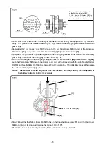
• Fix the hexagonal portion of the J-400 special socket. Fit the claws of the J-400 special socket in the
notches on the end surface of the Cylinder
[5]
. Loosen the Special Nut M58
[13]
and turn the Nose
[18]
to remove it from the Cylinder
[5]
.
Bit type
Tip shape
[11]
Temporarily tighten the
Nylock Bolts M6
[12]
so that
the threaded portion can be
seen 3.5 to 6.5 mm.
[11]
Reduction valve set
Fig. 18
[71]
[18]
Tape


