


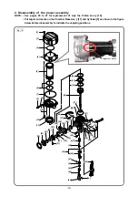


-13-
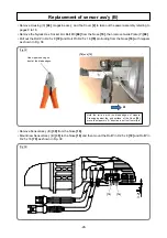
Fig. 11-1
Fig. 11-2
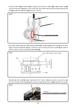
• Set the lock lever to the lock position to lock the trigger for
safety (Fig. 11-1).
• Mount the battery and adjust the Adjuster
[42]
according to the following procedure (Figs. 11-2 and 11-3).
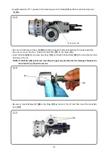
Press the Probe
[45]
against the 5.2 mm groove of the J-409 push lever gauge.
NOTE: Prevent the tip of the Piston Ass'y [16] from contacting the J-409 push lever gauge
(Fig. 12).
Hold down the power switch on the operation panel for 2 seconds and check that the power is turned
on.
When the power is not turned on, make a half turn of the Adjuster
[42]
to narrow the gap between
Pushing Lever (A)
[44]
and the Adjuster
[42]
, and repeat the above steps and .
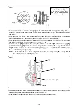
When the power is turned on, hold down the power switch for 2 seconds to turn off the power. Press
the Probe
[45]
against the 4.5 mm groove of the J-409 push lever gauge.
Hold down the power switch on the operation switch for 2 seconds and check that the power is not
turned on. When the power is turned on, check Sensor Ass'y (B)
[39]
referring to "Checking the
pushing lever operation (sensor ass’y (B) output)" on page 24.
NOTE: Prevent the tip of the Piston Ass'y [16] from contacting the J-409 push lever gauge (Fig. 12).
1
2
3
1
2
4
5
Lock lever
Yes
Adjustment completed.
Check Sensor Ass’y (B)
[39]
referring to page 24.
No
Is the power turned on?
Yes
Press the Probe
[45]
against the 4.5 mm
groove of the J-409 push lever gauge and
hold down the power switch for 2 seconds.
No
Press the Probe
[45]
against the 5.2 mm
groove of the J-409 push lever gauge and
hold down the power switch for 2 seconds.
Is the power turned on?
1
2
3
4
Make a half turn of the Adjuster
[42]
to
narrow the gap between Pushing Lever
(A)
[44]
and Adjuster
[42]
.
5


