


-19-
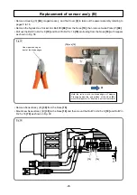
Fig. 21
• Remove Pushing Lever (B)
[40]
and Pushing Lever Spring (B)
[37]
.
• Remove the Special Bolt M6
[38]
and Adjuster
[42]
from Pushing Lever (B)
[40]
.
• Remove the two Nylock Bolts (W/Flange) M4 x 14
[36]
and one Nylock Bolt (W/Flange) M4 x 25
[27]
from
the Nose
[18]
, then remove Blade Guide (A)
[86]
.
• Remove the Nylock Hex. Socket Hd. Bolt M3
[69]
from the Nose
[18]
, then remove Guide Plate (P)
[68]
.
• Cut the two Wire Bands
[73]
that fix Sensor Ass’y (B)
[39]
and Sensor (C)
[67]
, then remove Sensor (C)
[67]
.
• Remove the Roll Pin D2.5 x 8
[72]
and Roll Pin D2.5 x 16
[70]
that fix Sensor Ass’y (B)
[39]
referring to
page 28.
NOTE: Sensor (C) [67] can be removed only after removing Blade Guide (A) [86].
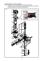
3. Reassembly of the power assembly
Reverse the disassembly procedure to reassemble. Note the following points:
• Use the specified tightening torques. (See page 31.)
• Protect the sealing parts (e.g., O-rings, X-rings, valve core, etc.) against contaminants and scratches
during reassembly.
• Always use brand-new seal lock bolts. Never reuse the old bolts.
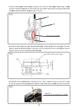
• Use the alignment marks (made before disassembly) for precise positioning when mounting the Chamber
Base Ass’y
[11]
on the Cylinder
[5]
.
• Slowly tighten the four Nylock Bolts M6
[12]
to fasten the Chamber Base Ass’y
[11]
and Chamber Cover
[4]
. Be careful not to pinch and damage the O-ring (I.D 94.5)
[7]
.
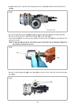
• Impregnate Felt (P)
[25]
with about 1 g of Molub-Alloy 777-1 grease by hand before reassembly.
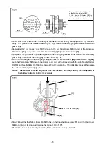
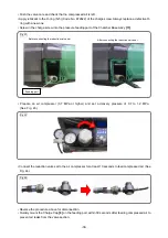
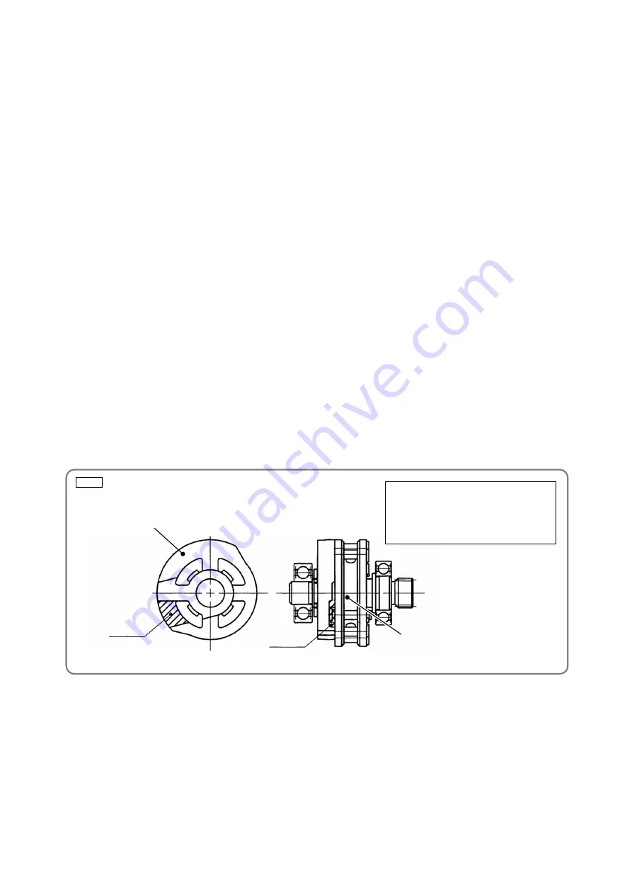
• Mount the Pin Wheel
[28]
to the Position Detector
[23]
so that the end surface side of Pin (A)
[34]
is
aligned with the notch of the Position Detector
[23]
as shown in Fig. 21.
NOTE: If the Position Detector [23] is not precisely located, an error (causing the orange LED of
the battery indicator to blink) may occur.
• Remove dust from between the Pin Wheel
[28]
and Needle Roller D3
[31]
and apply about 1.5 g of Molub-
Alloy 777-1 grease to the Needle Roller D3
[31]
, eight Needle Rollers D4
[33]
, and Needle Roller D4.5
[24]
evenly.
• Apply about 1.0 g of Isoflex Topas NB52 grease to the X-ring
[15]
and Slide Ring
[14]
of the Piston Ass'y
[16]
evenly.
Pay special attention to the position of
the Position Detector
[23]
.
If the Position Detector
[23]
is
misaligned, the standby position of the
piston is also misaligned. (See page 27.)
[28]
[23]
Notch
Notch


