


TP-6196 5/04
65
Section 6 Disassembly/Reassembly
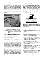
7. Remove the stator and rotor.
a. Remove the stator from the rotor.
b. Loosen and remove the thrubolt. Use a strap
wrench on the rotor to keep the rotor from
turning during loosening, if necessary.
See
Figure 6-11.
c. Remove the rotor assembly by striking the side
of the rotor repeatedly with a soft-faced
hammer
to
loosen
it
from
the
tapered
crankshaft fitting. See Figure 6-11. Rotate the
rotor and strike it on alternate sides. Set the
rotor assembly aside.
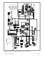
8. Remove the four engine adapter mounting bolts.
See Figure 6-12. Remove the generator adapter.
GM29253A-P
2
1. Thrubolt and magnetic actuator
2. Rotor strike surface
3. Generator adaptor
1
3
Figure 6-11
Rotor and Thrubolt
A-358000A-B
1
3
4
2
1. Generator adapter
2. Generator fan guard
3. Engine adapter mounting holes
4. Alternator adapter guard
Figure 6-12
Generator Adapter
6.2 Reassembly
1. Reinstall the generator adapter onto the engine.
a. Attach the generator adapter and alternator
adapter guard to the engine using four
7/16-14 x 1.0 hex cap bolts and washers. See
Figure 6-12.
b. Torque the bolts to 40 Nm (28 ft. lb.).
2. Install the rotor. See Figure 6-11.
a. Apply a small amount of antisieze compound to
the end of the engine crankshaft for rotor
assembly installation.
b. Install the rotor onto the engine crankshaft.
c. Thread the thrubolt through the actuator and
rotor into the crankshaft. Do not tighten the
thrubolt.
3. Install the stator and end bracket.
a. Align the stator so that the alternator frame
vibromount points down toward the generator
base.
See Figure 6-13.
Install the stator
assembly around the rotor.
b. Align the alignment mark on the top of the stator
slightly off-center of the slot in the generator
adaptor. See Figure 6-14. The small offset is
necessary in order to connect the muffler
bracket to the muffler later without interference.
GM29253A-F
1. End bracket
2. Alternator
3. Alternator frame vibromount
4. Overbolts
1
2
4
3
Figure 6-13
Generator Set, Right Side
Содержание 12RES
Страница 2: ......
Страница 24: ...TP 6196 5 04 14 Section 2 Scheduled Maintenance Notes ...
Страница 80: ...TP 6196 5 04 70 Section 6 Disassembly Reassembly Notes ...
Страница 92: ......
Страница 93: ......
Страница 94: ......
Страница 95: ......


