


TP-6196 5/04
58
Section 5 Component Testing and Adjustment
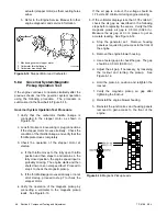
1. Battery power supply connection
2. Digital voltmeter (DVM) connection
3. Air/fuel control module connection
4. Oxygen sensor connection
GM-28981-
1
2
3
4
Figure 5-24
UEGO Sensor Interface Harness GM28981 Electrical Connections
10. Adjust the fuel metering valve as required to obtain
the output from the oxygen sensor specified in
Figure 5-26.
The output of the oxygen sensor
reads high when the mixture is fuel-rich and close
to zero volts when the mixture is lean.
11. Remove the load and allow the generator set to run
unloaded to cool for at least 5–10 minutes.
12. Place the generator set master switch in the OFF
position.
13. Disconnect the generator set engine starting
battery, negative (--) lead first.
14. Allow the generator set exhaust system to cool.
15. Disconnect the DVM leads from the oxygen
sensor.
16. Remove the oxygen sensor from the exhaust
manifold.
17. Apply a small amount of antiseize compound to
exhaust plug and reinstall the plug into the exhaust
manifold.
18. Check that the generator set master switch is in the
OFF position.
19. Reconnect the generator set engine starting
battery, negative (--) lead last.
20. Reconnect power to the battery charger.
1
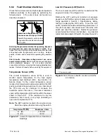
GM29253
1. Oxygen sensor mounting location
Figure 5-25
Oxygen Sensor Mounting Location
Oxygen Sensor Reading,
VDC
Model
Natural Gas
LP
8.5RES
2.40
±
0.05
2.25
±
0.05
12RES
2.60
±
0.05
2.60
±
0.05
Figure 5-26
Acceptable Oxygen Sensor Readings
Содержание 12RES
Страница 2: ......
Страница 24: ...TP 6196 5 04 14 Section 2 Scheduled Maintenance Notes ...
Страница 80: ...TP 6196 5 04 70 Section 6 Disassembly Reassembly Notes ...
Страница 92: ......
Страница 93: ......
Страница 94: ......
Страница 95: ......


