MIM-
MIM 01/0419
page
7
7. Mechanical connection
7.1 Check operating conditions
flow rate
max. operating pressure
max. operating temperature
In general, MIM is subjected to the same loads as the piping into which it is
installed. The MIM should therefore be kept away from extreme loads, such as
pressure surges with strong, dynamic pipe movements, vibrations in the proximity
of centrifugal pumps, high temperature media, flooding etc.
7.2 Installation
Remove all packing materials and transport retainers and ensure that no such
materials remain in the device.
It can be installed in vertical, horizontal or rising pipes. Flow in direction of the
arrow.
Avoid pressure and tensile load.
Mechanically secure the inlet and outlet pipe at a distance of 50 mm from the
connections.
Avoid valves or large reduction on the inlet section (this increases the
inaccuracy of measurements).
Check the leak tightness of the connections.
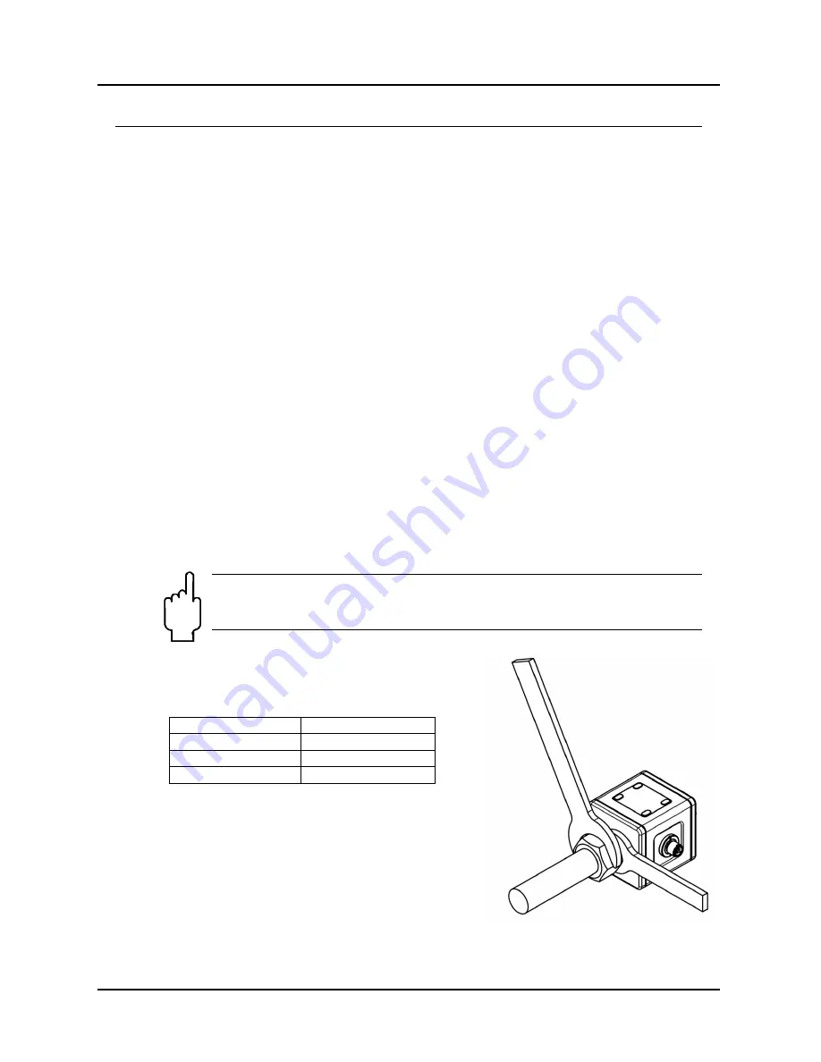
While mounting MIM hold the flowmeter from fitting surface (not
from the housing) with a wrench.
Take into account the tightening torque.
Nominal size
Tightening torque
½“
22 to 24 Nm
¾“
28 to 30 Nm
1“
28 to 30 Nm


