


TROUBLESHOOTING GUIDE
19
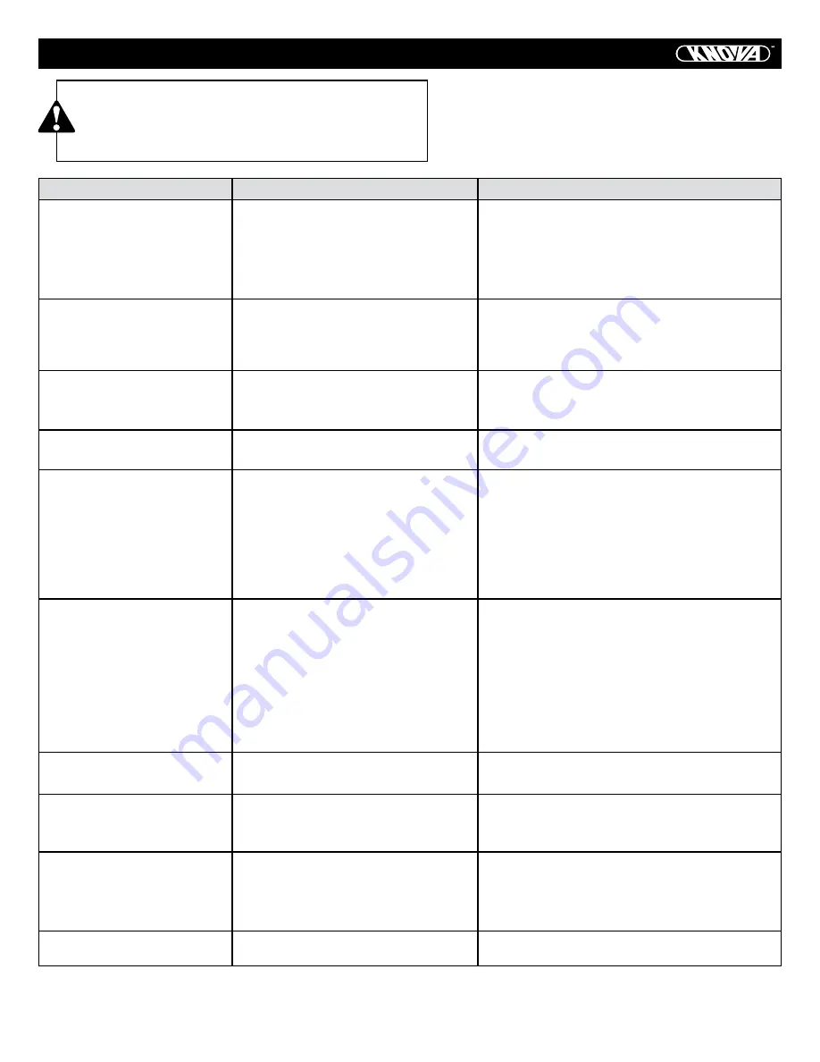
CORRECTIVE ACTION
1. Plug in saw.
2. Replace fuse or reset circuit breaker.
3. Replace power cord.
4. Remove switch from saw and separate in
half. Clean any debris accumulated within.
1. Check blade with square and adjust
positive stop.
2. Check blade with square and adjust to zero.
1. Check and adjust rip fence.
2. Select another piece of wood.
1. Check and align splitter with blade.
1. Replace blade.
2. Turn the blade around.
3. Remove blade and clean with turpentine
and coarse steel wool.
4. Change the blade.
5. Clean table with turpentine and steel wool.
1. Align rip fence with miter gauge slot.
2. Align splitter with blade.
3. Install and use rip fence.
4. Install and use splitter. (with guard).
5. Replace blade.
6. Push material all the way past saw
blade before releasing work.
7. Tighten knob.
1. Brush or blow out loose dust and dirt.
1. Replace with adequate size cord.
2. Contact your electric company.
1. Tighten all mounting hardware.
2. Reposition on flat level surface.
Fasten to floor if necessary.
3. Replace blade.
1. Adjust miter gauge.
SYMPTOM
Saw will not start.
Does not make accurate 45°
and 90° rip cuts.
Material pinched blade
when ripping.
Material binds on splitter.
Saw makes unsatisfactory
cuts.
Material kicked back from
blade.
Blade does not raise or tilt
freely.
Blade does not come up to
speed. Reset trips too
easily.
Machine vibrates
excessively.
Does not make accurate 45°
and 90° crosscuts.
CAUTION
To avoid injury from an accidental start, turn the switch
OFF and always remove the plug from the power source
before making any adjustment. If for any reason the motor
will not run, consult customer service.
POSSIBLE CAUSES
1. Saw not plugged in.
2. Fuse blown or circuit breaker
tripped.
3. Cord damaged.
4. Debris in on/off switch
1. Positive stop not adjusted
correctly.
2. Tilt angle pointer not set
accurately.
1. Rip fence not aligned with blade.
2. Warped wood, edge against
fence is not straight.
1. Splitter not aligned correctly
with blade.
1. Dull blade.
2. Blade mounted backwards.
3. Gum or pitch on blade.
4. Incorrect blade for work
being done.
5. Gum or pitch on blade causing
erratic feed.
1. Rip fence out of adjustment.
2. Splitter not aligned with blade.
3. Feeding stock without rip fence.
4. Splitter not in place.
5. Dull blade.
6. The operator letting go of material
before it is past saw blade.
7. Miter angle lock knob is not tight.
1. Sawdust and dirt in
elevation/tilting mechanisms.
1. Extension cord too light
or too long.
2. Low house voltage.
1. Saw not mounted securely
to workbench.
2. Bench on uneven floor.
3. Damaged saw blade.
1. Miter gauge out of adjustment.
Содержание KN BTS-10W
Страница 1: ...KN BTS 10W 10 254 mm Table saw with stand Sierra de mesa para madera con base...
Страница 23: ...EXPLODED VIEW 22...
Страница 48: ...DIAGRAMA DE ENSAMBLADO 47...
Страница 51: ...www knova com mx...


