DAD 6.1L/DAD 2.1L/MWD 2.1L user manual V6700, version 3.2
30
Optimizing the Detector
Connection
Undesired effects, like the loss of resolution in the chromatogram, may be
prevented by ensuring a correct connection to the flow cell and the removal
of any dead volume.
Remote Operation (Fiber Optics)
If the flow cell must be positioned outside of the detector (e.g. in an explo-
sion-proof room, at higher temperatures such as in an oven, or in an envi-
ronment with radioactive substances), the devices can be optionally
equipped with fiber optic connectors. Remote flow cells are recommended
for preparative applications (high flow rates), in order to protect sensitive
optical components from potential leakages.
For detectors with fiber optic cables the light intensity does not depend just
on the lamp and the cell but also on the quality / condition of the fiber optic
cables, the quality of the connections, the length of the fiber optic cables,
the number of bends and the bending radius.
Sensitivity is typically reduced to half that of an equivalent standard cell
when working with standard length fiber optic cables (750 mm). Overall,
sensitivity is inversely proportional to the length of the fiber optic cables.
Temperature changes around the cables may cause additional drift.
Selecting the Wavelength
Signal Wavelength
Wavelength selection can influence the sensitivity, selectivity and linearity of
a measurement. The measurement wavelength can be selected within the
range from 190–1000 nm for the DAD 6.1L or 190–700 nm for the DAD
2.1L and MWD 2.1L in 1 nm steps. The best wavelength for a given mea-
surement (signal wavelength) is that which fives the maximum absorption
above the UV cutoff of the mobile phase. In cases where there are multiple
components with different absorbance maxima, a compromise wavelength
must be chosen where all components absorb.
Baseline Correction / Refer-
ence Wavelength
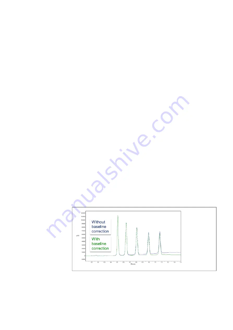
In order to minimize baseline drift due to refractive index effects, a reference
wavelength can be set in order to correct the baseline (see figure 26). The
reference should be set in the same spectral region as the signal wavelength
(UV or Vis) but at a wavelength at which the analyte has no absorbance.
Default Reference Wave-
length
By default, the reference wavelength 360 nm is activated (for channel 2).
This is a suitable value for most applications.
When selecting the signal and reference wavelengths, the respective band-
widths must also be selected (see the following section).
Fig. 26
comparison with and without baseline correction


