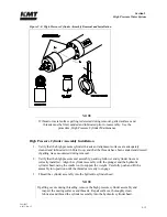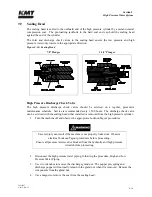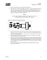
Section 9
High Pressure Water System
20412997
8-2012/Rev 12
9-19
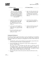
7/8” Diameter Plunger
1-1/8” Diameter Plunger
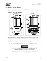
There are two holes in the sealing
head. The dowel pin on the poppet
retainer is positioned in one and the
inlet poppet is positioned over the
other. Ensure that the inlet poppet is
positioned over the
through
hole in
the sealing head.
4. Spray Loctite 7649 on the threads of the
retainer screws and allow to dry. Apply
one drop of Loctite 242 on the threads
only.
Do not
get any Loctite on the
poppet or any other surfaces on the inlet
check valve.
4. Spray Loctite 7649 on the threads of the
retainer screw and allow to dry. Apply
one drop of Loctite 242 on the threads
only.
Do not
get any Loctite on the
poppet or any other surfaces on the inlet
check valve.
5. Use the T20 star drive to tighten the
poppet retainer screws and torque to the
torque specifications in Table 9-1.
5. Use the wrench or socket to tighten the
poppet retainer screw. Tighten the poppet
retainer screw to the torque specifications
in Table 9-1.
6
Inspect the assembled unit to ensure the
poppet moves freely and the poppet
retainer screws are seated.
6. Inspect the assembled unit to ensure the
poppet moves freely and the poppet
retainer screw is seated.
Sealing Head Maintenance
The sealing head should be inspected for scratches, excessive sealing damage or erosion marking
on the cone ring contact surface, and on the inlet poppet valve contact surface. If defects are
detected, the surfaces must be refinished. The sealing head can be returned to KMT Waterjet for
refinishing.
1.
Clean the surface on the cone ring with 600-grit wet/dry sandpaper, using a radial motion.
It will not be possible to fully remove the main sealing marks.
2.
Inspect the inlet poppet valve sealing surface for pits, scratches or jetting erosion. If
necessary, refinish the surface.
Place a piece of 1/4-1/2” thick plate glass, not window glass, on a sturdy table to provide
an absolutely flat surface. Place a piece of 400-grit wet/dry sandpaper on the glass. Use
even, deliberate strokes, rotating the sealing head approximately 10-15 degrees after each
stroke. Polish the sealing head until it is flat and smooth. Be careful not to cause
additional damage by tilting or tipping the part while polishing.
3.
When the sealing head is flat and smooth, perform a final polish with 600-grit wet/dry
sandpaper.
Содержание Streamline SL-V 100 Plus
Страница 1: ...MANUAL 20413130 R13 STREAMLINE SL V 100 PLUS WATERJET INTENSIFIER OPERATION AND MAINTENANCE MANUAL ...
Страница 60: ...Section 4 Operation 20412948 8 2012 Rev 04 4 19 Figure 4 20 Language Screen ...
Страница 177: ...Section 12 Parts List 20413146 8 2012 Rev 12 12 5 Figure 12 1 SL V 100 Horsepower Intensifier Unit ...
Страница 179: ...Section 12 Parts List 20413146 8 2012 Rev 12 12 7 Figure 12 2 Intensifier Assembly ...
Страница 183: ...Section 12 Parts List 20413146 8 2012 Rev 12 12 11 Figure 12 5 Pneumatic Valve Actuator Assembly Normally Open ...
Страница 185: ...Section 12 Parts List 20413146 8 2012 Rev 12 12 13 Figure 12 6 Hydraulic Piston Assembly ...
Страница 187: ...Section 12 Parts List 20413146 8 2012 Rev 12 12 15 Figure 12 7 High Pressure Piping ...
Страница 189: ...Section 12 Parts List 20413146 8 2012 Rev 12 12 17 Figure 12 8 Low Pressure Water Filter Assembly ...
Страница 191: ...Section 12 Parts List 20413146 8 2012 Rev 12 12 19 Figure 12 9 Hydraulic Power Package ...
Страница 193: ...Section 12 Parts List 20413146 8 2012 Rev 12 12 21 Figure 12 10 Motor Pump Assembly ...
Страница 195: ...Section 12 Parts List 20413146 8 2012 Rev 12 12 23 Figure 12 11 Hydraulic Manifold Assembly ...
Страница 197: ...Section 12 Parts List 20413146 8 2012 Rev 12 12 25 Figure 12 12 Hydraulic Hose Connections ...
Страница 199: ...Section 12 Parts List 20413146 8 2012 Rev 12 12 27 Figure 12 13 Reservoir Assembly ...
Страница 202: ...Section 12 Parts List 20413146 8 2012 Rev 12 12 30 Figure 12 14 Bulkhead Pipe Assembly ...
Страница 203: ......
Страница 205: ...Section 12 Parts List 20413146 8 2012 Rev 12 12 32 Figure 12 15 Cover Assembly ...
Страница 207: ...Section 12 Parts List 20413146 8 2012 Rev 12 12 34 Figure 12 16 Electrical Assembly ...
Страница 210: ...Section 12 Parts List 20413146 8 2012 Rev 12 12 37 Figure 12 17 Controls Subassembly ...
Страница 211: ......
Страница 213: ...Section 12 Parts List 20413146 8 2012 Rev 12 12 39 Figure 12 18 Control Panel Configuration Wye Delta ...
Страница 215: ...Section 12 Parts List 20413146 8 2012 Rev 12 12 41 Figure 12 19 Control Panel Configuration Softstart ...
Страница 217: ...Section 12 Parts List 20413146 8 2012 Rev 12 12 43 Figure 12 20 Proportional Pressure Control ...
Страница 219: ...Section 12 Parts List 20413146 8 2012 Rev 12 12 45 Figure 12 21 High Pressure Transducer ...
Страница 221: ...Section 12 Parts List 20413146 8 2012 Rev 12 12 47 Figure 12 22 Redundant Kit ...
Страница 250: ......
Страница 251: ......
Страница 252: ......
Страница 253: ......
Страница 254: ......
Страница 255: ......
Страница 256: ......
Страница 257: ......
Страница 258: ......
Страница 259: ......
Страница 260: ......

