Section 9
High Pressure Water System
20412997
8-2012/Rev 12
9-22
8.
Remove the cylinder liner from the bore and inspect for possible heat or wear damage, or
for debris. If cracks or brittleness are detected on the tabs on the ends of the liner, the
liner must be replaced.
9.
Feel approximately one inch into the cylinder bore for obvious ridges or grooves. If seal
debris is present, follow the procedure, High Pressure Cylinder Maintenance.
10.
Inspect the plunger surface for flaws. Rotate the plunger 360 degrees by hand while
viewing light reflection on the surface to detect any dullness, streaks, pits or other defects.
Run a fingernail perpendicular to the direction of the suspected flaws to determine the
severity of defects. Depending on the seal life achieved with the removed seal assembly,
make a judgment regarding plunger and/or cylinder replacement. If seal debris is present
on the plunger, polish with 600-grit wet/dry sandpaper, using a radial motion.
11.
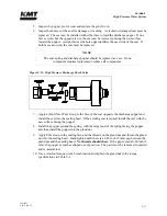
Lightly coat the new seal components with FML-2 grease and install the new components
on the plunger. Ensure the proper orientation of the backup rings as illustrated in Figure
9-13, High Pressure Seal Assembly.
12.
Slide the cylinder liner over the plunger.
13.
Install the high pressure cylinder assembly into the hydraulic cylinder head, following the
procedure, High Pressure Cylinder Assembly Installation.
14.
Reconnect the high and low pressure water piping and turn the low pressure water supply
on.
9.11
Hydraulic Cartridge Seal and Plunger Removal
The following procedure is used to remove the hydraulic cartridge seal and the plunger.
Prior to removing electrical power or any high or low pressure piping, start the machine from the
Maintenance Screen on the control panel. The machine will start in recirculation mode, the dump
valve will open and relieve the high pressure in the system.
Press the
RIGHT
or
LEFT
arrow to extend the plunger on the end to be serviced. The plunger will
extend in the selected direction, allowing full exposure when the unit is disassembled.
1.
Turn the machine off and observe the appropriate Lockout/Tagout procedures.
Severe injury can result if the machine is not properly locked out. Observe
electrical Lockout/Tagout procedures before proceeding.
Ensure all pressure is relieved or blocked from the hydraulic and high pressure
circuits before proceeding.
2.
Disconnect the high and low pressure water piping, following the procedure, High and
Low Pressure Water Piping.
3.
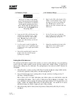
Remove the proximity switch on the end of the hydraulic cylinder to be serviced. This
will allow the hydraulic oil to drain back to the reservoir, minimizing oil spillage. It will
take approximately five minutes for the oil to drain.
Содержание Streamline SL-V 100 Plus
Страница 1: ...MANUAL 20413130 R13 STREAMLINE SL V 100 PLUS WATERJET INTENSIFIER OPERATION AND MAINTENANCE MANUAL ...
Страница 60: ...Section 4 Operation 20412948 8 2012 Rev 04 4 19 Figure 4 20 Language Screen ...
Страница 177: ...Section 12 Parts List 20413146 8 2012 Rev 12 12 5 Figure 12 1 SL V 100 Horsepower Intensifier Unit ...
Страница 179: ...Section 12 Parts List 20413146 8 2012 Rev 12 12 7 Figure 12 2 Intensifier Assembly ...
Страница 183: ...Section 12 Parts List 20413146 8 2012 Rev 12 12 11 Figure 12 5 Pneumatic Valve Actuator Assembly Normally Open ...
Страница 185: ...Section 12 Parts List 20413146 8 2012 Rev 12 12 13 Figure 12 6 Hydraulic Piston Assembly ...
Страница 187: ...Section 12 Parts List 20413146 8 2012 Rev 12 12 15 Figure 12 7 High Pressure Piping ...
Страница 189: ...Section 12 Parts List 20413146 8 2012 Rev 12 12 17 Figure 12 8 Low Pressure Water Filter Assembly ...
Страница 191: ...Section 12 Parts List 20413146 8 2012 Rev 12 12 19 Figure 12 9 Hydraulic Power Package ...
Страница 193: ...Section 12 Parts List 20413146 8 2012 Rev 12 12 21 Figure 12 10 Motor Pump Assembly ...
Страница 195: ...Section 12 Parts List 20413146 8 2012 Rev 12 12 23 Figure 12 11 Hydraulic Manifold Assembly ...
Страница 197: ...Section 12 Parts List 20413146 8 2012 Rev 12 12 25 Figure 12 12 Hydraulic Hose Connections ...
Страница 199: ...Section 12 Parts List 20413146 8 2012 Rev 12 12 27 Figure 12 13 Reservoir Assembly ...
Страница 202: ...Section 12 Parts List 20413146 8 2012 Rev 12 12 30 Figure 12 14 Bulkhead Pipe Assembly ...
Страница 203: ......
Страница 205: ...Section 12 Parts List 20413146 8 2012 Rev 12 12 32 Figure 12 15 Cover Assembly ...
Страница 207: ...Section 12 Parts List 20413146 8 2012 Rev 12 12 34 Figure 12 16 Electrical Assembly ...
Страница 210: ...Section 12 Parts List 20413146 8 2012 Rev 12 12 37 Figure 12 17 Controls Subassembly ...
Страница 211: ......
Страница 213: ...Section 12 Parts List 20413146 8 2012 Rev 12 12 39 Figure 12 18 Control Panel Configuration Wye Delta ...
Страница 215: ...Section 12 Parts List 20413146 8 2012 Rev 12 12 41 Figure 12 19 Control Panel Configuration Softstart ...
Страница 217: ...Section 12 Parts List 20413146 8 2012 Rev 12 12 43 Figure 12 20 Proportional Pressure Control ...
Страница 219: ...Section 12 Parts List 20413146 8 2012 Rev 12 12 45 Figure 12 21 High Pressure Transducer ...
Страница 221: ...Section 12 Parts List 20413146 8 2012 Rev 12 12 47 Figure 12 22 Redundant Kit ...
Страница 250: ......
Страница 251: ......
Страница 252: ......
Страница 253: ......
Страница 254: ......
Страница 255: ......
Страница 256: ......
Страница 257: ......
Страница 258: ......
Страница 259: ......
Страница 260: ......


