


Section 9
High Pressure Water System
20412997
8-2012/Rev 12
9-3
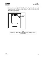
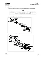
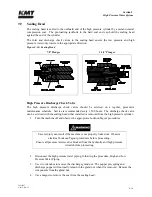
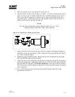
Figure 9-3: High Pressure Cylinder
Low pressure water is routed through the inlet water ports to the inlet passages in the sealing
heads. When the plunger retracts, the inlet check valve opens to allow water to fill the high
pressure cylinder. When the plunger extends to create high pressure water, the inlet valve closes
to seal the inlet passage and the discharge check valve opens to allow the high pressure water to
exit the cylinder. As the plunger retracts, the discharge check valve closes.
The intensifier is a reciprocating pump. As the piston and plungers move from one side to the
other, high pressure water exits one side of the intensifier as low pressure water fills the opposite
side.
The high pressure water is then routed to the attenuator. The attenuator acts as a shock absorber
to dampen pressure fluctuations and ensure a steady and consistent supply of water. From the
attenuator, the high pressure water exits to the cutting head.
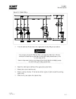
The safety dump valve releases the stored pressure in the intensifier and high pressure delivery
lines. The high pressure dump valve assembly includes a normally open high pressure water
valve and an electrically controlled air valve.
The normally open pneumatic dump valve is held closed by air pressure. When the air supply is
interrupted and exhausted from an emergency stop, the valve opens and allows water to flow
through the valve. Pressure is released in the intensifier and the high pressure water stream exits
through the drain.
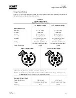
Redundant Intensifiers
If the machine is equipped with redundant intensifiers, the cutting water supply lines are
manually connected to the inlet water ports on the active intensifier. Manual hydraulic valves are
opened or closed to direct the hydraulic flow to the active intensifier. Manual high pressure water
valves are also opened or closed to direct the high pressure water flow from the active intensifier.
Control is switched from one intensifier to the other from the Run Screen on the control panel.
Содержание Streamline SL-V 100 Plus
Страница 1: ...MANUAL 20413130 R13 STREAMLINE SL V 100 PLUS WATERJET INTENSIFIER OPERATION AND MAINTENANCE MANUAL ...
Страница 60: ...Section 4 Operation 20412948 8 2012 Rev 04 4 19 Figure 4 20 Language Screen ...
Страница 177: ...Section 12 Parts List 20413146 8 2012 Rev 12 12 5 Figure 12 1 SL V 100 Horsepower Intensifier Unit ...
Страница 179: ...Section 12 Parts List 20413146 8 2012 Rev 12 12 7 Figure 12 2 Intensifier Assembly ...
Страница 183: ...Section 12 Parts List 20413146 8 2012 Rev 12 12 11 Figure 12 5 Pneumatic Valve Actuator Assembly Normally Open ...
Страница 185: ...Section 12 Parts List 20413146 8 2012 Rev 12 12 13 Figure 12 6 Hydraulic Piston Assembly ...
Страница 187: ...Section 12 Parts List 20413146 8 2012 Rev 12 12 15 Figure 12 7 High Pressure Piping ...
Страница 189: ...Section 12 Parts List 20413146 8 2012 Rev 12 12 17 Figure 12 8 Low Pressure Water Filter Assembly ...
Страница 191: ...Section 12 Parts List 20413146 8 2012 Rev 12 12 19 Figure 12 9 Hydraulic Power Package ...
Страница 193: ...Section 12 Parts List 20413146 8 2012 Rev 12 12 21 Figure 12 10 Motor Pump Assembly ...
Страница 195: ...Section 12 Parts List 20413146 8 2012 Rev 12 12 23 Figure 12 11 Hydraulic Manifold Assembly ...
Страница 197: ...Section 12 Parts List 20413146 8 2012 Rev 12 12 25 Figure 12 12 Hydraulic Hose Connections ...
Страница 199: ...Section 12 Parts List 20413146 8 2012 Rev 12 12 27 Figure 12 13 Reservoir Assembly ...
Страница 202: ...Section 12 Parts List 20413146 8 2012 Rev 12 12 30 Figure 12 14 Bulkhead Pipe Assembly ...
Страница 203: ......
Страница 205: ...Section 12 Parts List 20413146 8 2012 Rev 12 12 32 Figure 12 15 Cover Assembly ...
Страница 207: ...Section 12 Parts List 20413146 8 2012 Rev 12 12 34 Figure 12 16 Electrical Assembly ...
Страница 210: ...Section 12 Parts List 20413146 8 2012 Rev 12 12 37 Figure 12 17 Controls Subassembly ...
Страница 211: ......
Страница 213: ...Section 12 Parts List 20413146 8 2012 Rev 12 12 39 Figure 12 18 Control Panel Configuration Wye Delta ...
Страница 215: ...Section 12 Parts List 20413146 8 2012 Rev 12 12 41 Figure 12 19 Control Panel Configuration Softstart ...
Страница 217: ...Section 12 Parts List 20413146 8 2012 Rev 12 12 43 Figure 12 20 Proportional Pressure Control ...
Страница 219: ...Section 12 Parts List 20413146 8 2012 Rev 12 12 45 Figure 12 21 High Pressure Transducer ...
Страница 221: ...Section 12 Parts List 20413146 8 2012 Rev 12 12 47 Figure 12 22 Redundant Kit ...
Страница 250: ......
Страница 251: ......
Страница 252: ......
Страница 253: ......
Страница 254: ......
Страница 255: ......
Страница 256: ......
Страница 257: ......
Страница 258: ......
Страница 259: ......
Страница 260: ......